Continue to Site

Welcome to our site!

Electro Tech is an online community (with over 170,000 members) who enjoy talking about and building electronic circuits, projects and gadgets. To participate you need to register. Registration is free. Click here to register now.

  • Welcome to our site! Electro Tech is an online community (with over 170,000 members) who enjoy talking about and building electronic circuits, projects and gadgets. To participate you need to register. Registration is free. Click here to register now.

Alternator - Jeep Cherokee 1997

Status
Not open for further replies.

b.james

Member
I have just blown my second alternator in 3 years. Its the type that the field winding is controlled by the engine management chip.
The controller is OK I'm thinking but the two alternators show different signs and I am trying to get one to work.

"A" gives an output voltage of up to 18 volts when run as fast as my drill can turn it and the field is taking about 4 amps directly through my bench supply at 12 Volts. Can't get it over 18V but my drill is a bosch 1200 watt on 240 V so I guess its doing about 900 rpm or less

"B" gives no output at any speed and takes about the same amperage through the field winding .

I have checked all the diodes and all seem to be working fine.
I have noted that on "B" None of the windings show a resistance at all and show continuity with a buzzer. I havn't checked "A" diodes again but they seemed OK the first time I checked them. However the windings again gave no resistance however I checked them , just continuity.

Can anyone lay out a definitive check routine so I can locate the faults?
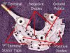
With the 3 windings being joined at the star center I would have thought some sort of testable resistance should show if I can get continuity between any two windings
 
Last edited:
How good is your meter at measuring very low resistances (which the main alty windings would be)?
 
As Alec says the winding will be a very low resistance. If the 3 phase bridge rectifier is still connected to the winding and some or all of the diodes have failed then that could short out the windings as diodes very often fail to a short circuit. I think 900 rpm is probably less than the alternator would be rotating a tickover as theu are normally geared up from engine speed. The pully on the alternator is quite small compared with the one on the engine. You could disconnect the rectifier and measure the AC voltage between the three ends of the windings.

Les.
 
It takes about 3000rpm at the alternator shaft for it to do much. As pointed out, with the pulley ratios actually used in vehicles, even with the engine idling at 800RPM, the alternator will be spinning at >2000rpm. At highway speeds, the alternator is turning almost 10,000 rpm.
 
The "A" alternator "on the surface is working".

he "B" alternator, not so much.

Watch "No resistance". I believe your saying no means "zero" where zero is the lowest number your meter measures. Zero is unattainable. Open/shorted , infinite/very low are better terms.

That aside, you really have the winding resistance, the insulation resistance or unintended shorts to the other windings or turn shorts.

Measuring ripple with a scope is a good way to see shorted diodes.

Brushes to the rotating field are another area. The voltage drop across the brush can be checked. I had one alternator break a connection at the rotor.

One was bad enough from age that it really had to be re-wound. The alternator was like 16 years old.
One had a bearing issue - obvious.

Diode failures are common.

The BIGGEST problem of all is loose connections and sometimes in the oddest places. Had car painted, the shop did tighten the battery cable. Can cause failure of diodes.

The oddest failure was corrosion on a bulkhead connector. That was killing alternators. Watch battery crimp connectors.
 
Well thanks but not much gained there. Alec-t I need to find then that resistance to be sure it is not shorted out between the static windings. How can I do that with a cheap multimeter? I need to see a resistance for each coil.Its a wye formation I think .

How in practical terms can I check the diodes? I'll try attach a picture of the bridge . What do I check where? I could only find one with 6 diodes . Mine has 8
 

Attachments

  • 12f.jpg
    12f.jpg
    48.4 KB · Views: 318
  • 19b.jpg
    19b.jpg
    48.5 KB · Views: 343
It takes about 3000rpm at the alternator shaft for it to do much. As pointed out, with the pulley ratios actually used in vehicles, even with the engine idling at 800RPM, the alternator will be spinning at >2000rpm. At highway speeds, the alternator is turning almost 10,000 rpm.
No actually its about 2 to 1 judging by the pulleys so 2000rpm motor = 4000rpm alternator
 
You could disconnect the rectifier and measure the AC voltage between the three ends of the windings.

Les.
Thats doable but dificult but what a/c voltage could I expect then . At the same revs i would expect about 18V also ? I suppose if it were a lot higher that might indicate a diode bridge rectifyer problem though Hmm .
 
Can you post a link to your "cheap' multimeter? Lowest DC volt scale? Digital?

Does it actually have a diode test mode?

If you don;t have a diode test, you can take a 9V battery and something like a 1K resistor. Attach the network to the battery and measure the voltage across the diode in both directions. You can also measure what the DVM thinks the resistor is. The alternator could be 4 phase although I have never seen one.

With windings connected finding a short would be difficult without a milli-ohmmeter. A brake lamp, a resistor and a 12 V power supply should work. We'd have to work out what you might need to measure the "voltage across a winding" and the "current through" a winding and calculate the resistance. The light bulb would basically be protection.

You can get a current sensor such as https://www.robotshop.com/en/pololu-5a-acs715-current-sensor.html and a 5V wall wart to also measure current.

A stabilized voltage isn;t needed as long as you measure both voltage and current. R=V/I is resistance.

14 AWG wire is about 2.5 ohms per 1000 ft. See https://www.powerstream.com/Wire_Size.htm

So each winding would be measured separately and then the series connection. You would look to make sure that 3*x is valid and that the resistances of each winding is about the same.

This https://www.harborfreight.com/7-function-multimeter-98025.html is a cheap multimeter.
 
The BIGGEST problem of all is loose connections and sometimes in the oddest places. Had car painted, the shop did tighten the battery cable. Can cause failure of diodes.

The oddest failure was corrosion on a bulkhead connector. That was killing alternators. Watch battery crimp connectors.

+1. I had a '99 Trans Am that probably put O'reilly Auto Parts in the red for fiscal year 2008. I must have went through at least 8 alternators under warranty. I got more and more irritated each time, blaming the "cheap" quality of their alternators. Until maybe #5, then I started to suspect there might be more to the story. I couldn't find any problem though; alternator was putting out stead voltage every time I tested, battery was good, had it tested, and went ahead and replaced it even though they said it was good. I wasn't blowing any fuses and everything on the car was working perfectly. But seemingly every time I got over 5000RPM I was running a 50% chance of blowing my alternator.

I had it in to a couple of mechanic shops and they could find nothing wrong with it. ended up taking it to a "F-body" performance shop and they told me it was a bad ground cable. They showed me the cable, I didn't see anything wrong with it. I walked away pissed that I had just paid $200 in labor, and paid for a cable I didn't need. I felt scammed. But my alternator never blew again. WTF?! That fixed it. Those guys knew what they were talking about after all. One more bullet to the list of reasons why I hate automotive electrical.
 
There is another possibility for "B" assuming you get the no resistance sorted out. You have a magnetic field. Any possibility, the polarity was backwards?

Here, assuming an cheap analog meter that won;t read a negative voltage. Is it possible that the polarity to the rotor was backwards for a brief instant? This "could" magnetize the rotor in the wrong direction. Somewhat gasping at straws.

It's likely you don't have a scope. All the diodes shorted would cause no output. Rotor current suggests the brushes are good enough.
 
I've definitely replaced the battery ground cable.

It used to be possible to rebuild alternators. My Toyota alternator had spot welded components in it. You just get upset because you can't pin the loose battery connection on the body shop that painted your car. the blown alternator can cascade into a bad battery.

This story would piss you off too;
The car was sitting for about 5-10 weeks. I jumped it and it was OK. I also did a Hygrometer check and got low readings.

When the car was in for service, I asked the dealer to test the battery. they said the battery was "fine". The next day I drove it 50 miles away and the car would not start after I reached my destination. My appointment was for an hour and the car started after my appointment. I went to another destination and it sort of did the same thing.
I called my insurance company and they picked out a service shop and I was towed there. They said the alternator belt snapped. they tested the battery and said "It was fine". I drove the 50 miles home. The next day the car would not start. Guess what - the battery was bad,

The dealer doesn't even have a battery hygrometer. The battery university website says that electrical test can yield false positives. I actually have a commercial battery load tester as part of a charger. Talk about being annoyed.

The good part is that it was a nice day and it didn't impact the parking fee much and it was in an open lot. The very good part is that the car did not stall in the metropolitan city I was in. I also got to eat in a nice diner before going home.

==

The corroded bulkhead connector (those 50 pin ones) was in a 70's Chevy and it was a real bear to find.
The sudden break of the rotor connection was a total surprise. The car just stopped.
I miss the voltmeter/discharge light that one of my Toyota's had.
 
Gone stale here .
Does anyone else have any suggestions as to how to test the diode bridge shown and be sure it is right?
Its not easy to work out which diode is connected to which and which are positive and which negative. They are all in conducting and non conducting layers and coated with a ceramic layer for heat protection
 
Last edited:
Yeh yeh stop with the **** and start making this site sensible and useful . Look at the crap in this thread now as an example of where you clowns are taking this forum
 
Interesting blurb: https://alternatorparts.com/external-voltage-regulator-high-output-alternator-kit.html Don't lnow what to make of it.


Generally, you would disconnect the diodes from the alternator coils and test each one in the forward and reverse directions using the diode test on your meter.

Some strange connections: **broken link removed**
The first is a solution when your car computer breaks down . This is not my case as above says.
The second is a truck alternator and bears no resemblance

Why do you keep posting crap
Can't you just go away when given a hint and let someone else have a go .
All you serve to do atm is block other people from commenting because they see an answer there .

With 8900 posts You must be quite aware of what you are doing to the forum and each thread . You obviously just sit on here each day and do not have a life to go to.
 
Last edited:
MikeM "I am an engineer and an academic. When I talk about current it flows from positive to negative."

But it does not mike as you know and that stubborn head in the sand approach holds back the younger generations by confusing them . Its now being taught properly in Unis so move with the times is my way - no offence intended Mike
 
OK, so you belong in the category of the dinosaur that needs feeding. Maybe you'll be the first to be put on my ignore list.

In a professional publication known as Intech which is the magazine for International Society of Automation there was an editorial where the method of of "throwing out crap" when brainstorming was discussed as a poorly understood but VALUABLE method of designing stuff which management doesn;t understand.

You have to realize that while we have the ability to troubleshoot we lack robotic arms and eyes. I think I asked if you had a meter with a diode tester mode? No answer.

Once you have the bridge out, the diodes are connected in a fashion where they can be tested. You just have to be able to locate both ends.

So, Diode test each diode, in both directions and record the results. If you don;t have a diode tester, then use a 9V battery, a 1K resistor and a voltmeter.

Did you do that? NO!! There is at least no indication that you have.

One of your alternators, on the surface may be partially good. It may lack full output. e.g. a diode could be shorted. Easy to tell on a scope.

I don;t have any idea where 8 diodes comes from.

BOTTOM LINE: You have to test each diode.

If you happen to test the diodes on the rx1 scale and they happen to be shorted in both directions. It;s bad.

There's a lot of tests that when used determine BADNESS, but few tell whether or not the device works correctly.

So, I posted about an external regulator. You say what does that have to do with sliced bread? I say maybe the regulator in the ECM is fried. Maybe it's a more permanent fix. It describes some alternators that I did not know about (tach signal). Someone may have replaced the incandescent bulb in the dash with a LED and it's likely that won't work. The info offers a new twist or a new direction.

Test the diodes in both directions and record Vf. provide that table and we can go from there.

Swap the bridges and see if the problems switch positions.

Most failures are due to loose connections in the car's electrical system. The alternator is a symptom and not a problem. Age generally can point to alternator problems.

A shorted diode generally means one of two issues:
1) batteries run down at rest
2) Not enough output.


The devices are simple. One thing that must happen is the rotor must be "electrically disconnected" when the engine is not running.

My answers were not unrelated. I'm sorry that your education has taught you "What to think" instead of "How ro think". I don't think you described what the "bad alternator" symptoms were?

I use these tests on the vehicle:
1) voltmeter under various conditions (no load, full load)
2) Specific gravity of battery
3) A scope to measure ripple.
4) Inspection - loose connections
5) Measure across connections.
6) Charging current.
a) I may measure the voltage from the battery to alternator when the system is good and compare when troubleshooting. Now I have a DC clamp meter.


Gone stale here .
Does anyone else have any suggestions
Yeh yeh stop with the **** and start making this site sensible and useful . Look at the crap in this thread now as an example of where you clowns are taking this forum
MikeM "I am an engineer and an academic. When I talk about current it flows from positive to negative."

But it does not mike as you know and that stubborn head in the sand approach holds back the younger generations by confusing them . Its now being taught properly in Unis so move with the times is my way - no offence intended Mike

Why do you keep posting crap
Can't you just go away when given a hint and let someone else have a go .
All you serve to do atm is block other people from commenting because they see an answer there .
You obviously just sit on here each day and do not have a life to go to.

Yeah because folks were just lined up begging for the chance to spoon feed you answers before he/we showed up and tried to help.
Congrats on killing your own thread, you're an ungrateful twat. Good luck!
 
Status
Not open for further replies.

Latest threads

New Articles From Microcontroller Tips

Back
Top