Hi folks,
I noticed a fault on this unit in my local coffee shop, so I offered to fix it. After all I've lots of experience, how hard could it be?
**sigh**
So the issue is that when the dryer is first powered on it runs immediately and the timer counts down from 10 seconds to 0. However the dryer continues to run for about 10 seconds more and then shuts down with a flashing error LED and displaying E2, which means "Take your hands out of the dryer!"
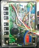
It seemed so simple. After all it's just a motor, a heater and s timer, the whole thing triggered by an infra-red LED and a photo-transistor. Unfortunately I opened up the electronics and found this:

Sorry, for some reason I can't seem to embed a Flickr image, so please forgive the attachment.
Basically there's a helluva lot of stuff in there. The power semiconductors on the heatsink drive the DC brushless motor at a quite spectacular speed of 30,00+ RPM (I believe). The rest of the kits seems seriously over-complex for what the machine does, but the build quality is very high. Unfortunately that means that the entire board is lacquered on both sides to prevent corrosion.
The hand detector circuit is quite simple. It consists of four IR LEDS in series at the top front of the hand slot and three photodiodes on another (very tedious to remove) board at the lower rear of the slot. The photodiodes seem to be similar to **broken link removed** . They appear to be connected between 12V and eventually to the non-inverting inputs of an SM LM324 as shown in the .png file attached. I haven't had much luck tracing the circuit fully due to the dense packing of the SMDs.
I'm struggling at this point because my oscilloscope is on the blink and the IR has to be modulated to avoid daylight, so I presumably can't simply short the photodiodes to simulate full illumination.
It's a long shot, but does anyone have any experience of these or similar circuits?
I noticed a fault on this unit in my local coffee shop, so I offered to fix it. After all I've lots of experience, how hard could it be?
**sigh**
So the issue is that when the dryer is first powered on it runs immediately and the timer counts down from 10 seconds to 0. However the dryer continues to run for about 10 seconds more and then shuts down with a flashing error LED and displaying E2, which means "Take your hands out of the dryer!"
It seemed so simple. After all it's just a motor, a heater and s timer, the whole thing triggered by an infra-red LED and a photo-transistor. Unfortunately I opened up the electronics and found this:
Sorry, for some reason I can't seem to embed a Flickr image, so please forgive the attachment.
Basically there's a helluva lot of stuff in there. The power semiconductors on the heatsink drive the DC brushless motor at a quite spectacular speed of 30,00+ RPM (I believe). The rest of the kits seems seriously over-complex for what the machine does, but the build quality is very high. Unfortunately that means that the entire board is lacquered on both sides to prevent corrosion.
The hand detector circuit is quite simple. It consists of four IR LEDS in series at the top front of the hand slot and three photodiodes on another (very tedious to remove) board at the lower rear of the slot. The photodiodes seem to be similar to **broken link removed** . They appear to be connected between 12V and eventually to the non-inverting inputs of an SM LM324 as shown in the .png file attached. I haven't had much luck tracing the circuit fully due to the dense packing of the SMDs.
I'm struggling at this point because my oscilloscope is on the blink and the IR has to be modulated to avoid daylight, so I presumably can't simply short the photodiodes to simulate full illumination.
It's a long shot, but does anyone have any experience of these or similar circuits?