Continue to Site

Welcome to our site!

Electro Tech is an online community (with over 170,000 members) who enjoy talking about and building electronic circuits, projects and gadgets. To participate you need to register. Registration is free. Click here to register now.

  • Welcome to our site! Electro Tech is an online community (with over 170,000 members) who enjoy talking about and building electronic circuits, projects and gadgets. To participate you need to register. Registration is free. Click here to register now.

Advise Needed

Status
Not open for further replies.

codan

New Member
Hi All,

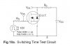
I want to try to test the switching time of the IRFP450A Mosfet & others to learn more about things. I have attached the recomended test circuit.
Where it has Vds & Vgs on the schematic, do i need to connect anything to these two points?

Can somebody point me to a 555 timer circuit to create a clean "Rectangle" waveform as this is what i would like to test the Mosfets with.
If possible i would like to have a 0v to 15v peak output signal & not to go negative if that makes sense, my supply voltage is 12v. I would like to vary the frequency etc but as i take it this can be done with different caps etc.

Thanks
 

Attachments

  • IRFP450A Mosfet.jpg
    IRFP450A Mosfet.jpg
    14.3 KB · Views: 162
Last edited:
Lot of 555 osc circuits are there in google. Try googling. A BD139 or 2N3055 power transistors will give you amplified output.
 
The old 555 is too slow and doesn't have enough output current to test the very fast switching time of Mosfets.
 
You should use a Mosfet driver IC to switch Mosfets as fast as is possible. I don't know one and I don't know if Mosfets can switch faster than the fast driver IC.

Why do you want to test the switching times? The datasheet lists them. The gate capacitance charge is fairly high and is also listed. It is difficult to charge and discharge it quickly.

I am only 13yrs old & some of the data sheets & terminology i do not understand yet so for me at this stage testing things is a way to understand what the heck there talking about?

I have attached the data sheet, could you help me through it please.

The switching time i guess is the rise & fall time--is this correct?

Basically i need to know how fast this Mosfet can be switched on & then off, from 0v to peak & then back to 0v.

I am attempting a project with a circuit that has a rectangle wave output of 0v to 15v peak.
I want to trigger a Mosfet or Transistor or similar from this waveform on the rising voltage of the rectangle wave & amplify this as much as i can to obtain a higher output.
I need the amplifier circuit to be able to switch on with as little time delay as possible, rise to peak & back to 0v in .1mS or less.

Hope this makes sense.
 

Attachments

  • Data.gif
    Data.gif
    52.8 KB · Views: 157
Last edited:
You selected a high voltage low current Mosfet. Because its current is low then its gate capacitance is low so it does not need a high current to charge the capacitance quickly.
With a "perfect" high current gate pulse, its typical total turn on time is 15ns + 36ns= 51ns. Its typical total turn off time is 35ns + 29ns= 64ns. The total on and off times is 51ns + 64ns= 115ns which is 0.115us.
If the output voltage goes low then goes high again without staying low then its total switching time of 0.115us is 870 times faster than 0.1ms.
 
Status
Not open for further replies.

Latest threads

New Articles From Microcontroller Tips

Back
Top