ploppyboom
New Member
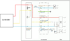
Hi, I have an EC Motor controller which monitors ambient temperature and adjusts the EC motor speed via the DC10V signal wire. After measuring, this wire will send anything from DC0V (OFF) - DC7V (100%) to control the fan speed.
My issue is that the controller switches OFF (0V on the signal wire) when a particular temperature is reached, whereas I want it to remain running at a particular speed.
So basically I want to hack this circuit and insert another circuit on the signal wire, which will ensure voltage never drops below a particular threshold, ie 2v.
This would in effect make the fan continue running at about 20% speed even when the original controller is sending 0V down the wire. The controller is powered by DC10V coming from the motor so I have this as the power source.
Having scoured the internet I am unable to name such a component/circuit. Is it an inverting voltage comparator I need perhaps?
Bonus cookie points if I could adjust the threshold point/output voltage via a potentiometer or similar.
Extra bonus cookie points if such a circuit already exists and I can buy it without having to solder a single component apart from power and signal wires.