Electro Tech is an online community (with over 170,000 members) who enjoy talking about and building electronic circuits, projects and gadgets. To participate you need to register. Registration is free. Click here to register now.
Welcome to our site! Electro Tech is an online community (with over 170,000 members) who enjoy talking about and building electronic circuits, projects and gadgets. To participate you need to register. Registration is free. Click here to register now.
This is the wave form on the DC output loaded 20mv/div vert. No load 5mv/div vert. With a 1000uf cap on output 5mv/div vert. Also one ive fitted to a VHF hand held tranciever to run it of 12v.
Here's a photo of one of these buck modules modified to be a LED driver, driving 3 watt LED at just under 700 ma, LED is rated for 800 ma, so it should last quite a while, I'll probably get to pass this on to my kids or grand kids.
OK, I've actually used a couple of the little regulators now, both on identical little boards, in order to provide external power to tutorial boards via the PICKit3 programmer connection. I've added a picture of the board (the socket connector strip also came from Bangood), a picture of it connected to an 16F1827 tutorial board (nothing there from Bangood), and also a picture of my new LCD tutorial board, using an LCD from Bangood.
Having used a number of those inexpensive Ebay switchers (w/out the metering) - some of which look exactly like the ones in the picture - I can say that they are certainly worth the price, which is less than that for which I can get the parts!
I did build one of these into a device that runs 24H/7D and noting that various parts of these ran "very warm" I:
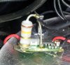
- Paralleled high-quality, low-ESR capacitors (470uF) on the input and output sides to take some of the stress off the unknown (!) quality capacitors on these boards. (I used Panasonic caps, IIRC).
- Soldered a reasonably large piece of copper bent to an "L" shape to the tab of the IC (such as it is!) to improve heat-sinking.
- Using "JB-Weld" - a metal-filled epoxy capable of reasonably high temperatures, I attached a piece of aluminum bent to a "U" shape to the top of the inductor to get rid of some of its heat which was being transferred to its adjacent components.
Just adding the additional capacitors made a disproportional improvement in the reduction of the switching energy (like that on the pics from the CRO) on the input/output leads - more than you'd expect from the increase in capacitance - implying that the onboard units are probably a bit higher impedance than the new, outboard units. This may have meant that they would be dissipating a bit of heat on their own, probably resulting in reduced lifetime. For as cheap as they are, I wasn't counting on them having very good capacitors (or enough capacitance!) anyway!
My non-contact IR thermometer showed an approximate 10C drop in device temperature after adding the additional heat sinks. This cheap converter has been running 24/7 for about 2 years near its maximum ratings, so that's something!
This site uses cookies to help personalise content, tailor your experience and to keep you logged in if you register.
By continuing to use this site, you are consenting to our use of cookies.

")