Continue to Site

Welcome to our site!

Electro Tech is an online community (with over 170,000 members) who enjoy talking about and building electronic circuits, projects and gadgets. To participate you need to register. Registration is free. Click here to register now.

  • Welcome to our site! Electro Tech is an online community (with over 170,000 members) who enjoy talking about and building electronic circuits, projects and gadgets. To participate you need to register. Registration is free. Click here to register now.

Active loading for measuring high currents

Status
Not open for further replies.

BrianG

New Member
I need an adjustable loading circuit so I can load test various batteries from 1A up to 100A at various current increments. Using resistor networks to achieve the various loads is not very efficient or accurate so I thought using MOSFETS or transistors as an active load could be used for this.

What I'm trying to do is determine the discharge capability and voltage drop of certain batteries at various load currents. The batteries I'll be dealing with are 1.2v NiMH/NiCD and 3.7v Lithium Polymers for use in R/C applications where current draw can be very substantial.

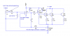
To give you an idea of what I've come up with so far (and to show I'm actually trying, not just seeking an easy answer); Put a precision .01 ohm shunt resistor at the emitter of an NPN transistor, the battery to test as the transistor's supply, and a highly accurate voltage supply to drive the base. As the base voltage increases, it will increase the voltage at the emitter, and therefore across the .01 ohm resistor. The transistor will drop the rest of the voltage. I can then measure the voltage across this resistor, which corresponds to the current. I can then measure the battery voltage to see how much it drops as current increases. However, most transistors aren't capable of 100A and I'd have to take the base current into consideration (which could be substantial) for my driving voltage circuit. The resistor is just an example. I have a VERY large heatsink for the active device(s) already and have a few fans to help cooling. These test measurements will only be for about 10 seconds at a time.

Also, I know the dangers of exceeding the current ratings of these batteries, so I will be careful. The battery under test will be in an aluminum box for safety.

Any ideas on an accurate circuit for this? Can I simply parallel transistors? If I do so, how do keep one from conducting more than the others (due to parameter tolerances) hogging the current until that one blows? Can MOSFET(s) be used instead? There has to be a more elegant solution.

Thanks in advance!

(And no, this isn't a homework assignment, just a project for my hobby :))
 
BrianG said:
Can I simply parallel transistors? If I do so, how do keep one from conducting more than the others (due to parameter tolerances) hogging the current until that one blows? Can MOSFET(s) be used instead?

You simply include resistors in the emitter of each transistor, this balances the load across all the transistors. You can use MOSFET's instead, it's really a matter of personal preference, and what you have available!.
 
If you really want to be sure your load current is equally distributed, this will do it. It will also allow you to control the current predictably by setting the control voltage. You may want to adjust the number of stages. The current per stage is vctrl/R1.
I'm assuming you know how to choose the transistor.
 

Attachments

  • active_load.png
    active_load.png
    9.8 KB · Views: 956
Thanks guys!

I knew I could put a small resistor at the emitter of each transistor, but that would make it hard to measure the voltage drops on all the emitter resistors at once (to be sure I am pulling the exact current I'm testing). Is there a way to directly parallel each output device (transistor or MOSFET) so I only need one shunt resistor? Since we are talking about high currents, low voltages/resistances, any deviation in tolerances in the shunts will create errors in the current calculations.

Oh, and, I had made a mistake in my original question. I'd have to use a .001 ohm shunt otherwise I'd never be able to draw 100A if the battery falls below 1v (which it will).

I want to use one shunt so I can put my meter across the shunt resistor and adjust the control voltage. The current would actually be the measured voltage x 1000 since I'm using a .001 ohm resistor. Convenient. Another meter will be hooked to the battery so I can quickly get the battery voltage.
 
The problem with doing it without the op amp in the feedback loop is that your transistors will heat up in 10 seconds, and the base-emitter voltage (or gate-source voltage) will change drastically over that time, causing the current to change over time also. I think the circuit below would work. It still has emitter ballast resistors, but the current is sampled in the 0.001 ohm resistor and compared with the control voltage. The op amp forces the voltages at its inputs to be equal.
 

Attachments

  • active_load4.png
    active_load4.png
    16.3 KB · Views: 705
Hmmm, I see your point about the feedback. I'll give that a try. Thanks!

By the way, what's a "Kelvin-type connection" in your schematic? I read a little about it, but all I got from is that there is a sense and source connection and don't know what that means. At a guess, there are two sets of connections; one set for the high current, and one to take the voltage measurement? If so, why not simply take the measurement from the same connection as the high current one? Sorry for getting off track here...
 
You can use the same connections. The point is that none (or very little) of the measured current flows in the measuring circuit, and the voltage drop in the high current wires is not measured.
 
Where are you getting a 1 milliohm, 10 watt resistor? :?
Keep in mind that solder connections and copper will have resistances on the same order of magnitude. It is important to measure the drop across the 1 milliohm only, and not include voltage drop of any of the series parasitic resistance. See below.

Keep in mind also that, if you want to make your load as low as 1 amp, you will need an op amp with less than 0.1mv input offset voltage.

Edit: Russ, looks like you were posting while I was composing. :)
 

Attachments

  • kelvin.png
    kelvin.png
    6.4 KB · Views: 868
Oh ok, that makes sense. I guess any little bit of resistance matters once you start dealing with such low resistances! Thanks for clearing that up. My guess was half right, I just didn't see why. :)

Ron H said:
Where are you getting a 1 milliohm, 10 watt resistor?...
You weren't talking to me, right?
 
Hi Ron,

I think your current regulator would work better if you swaps the two inputs to the op-amp.
 
eblc1388 said:
Hi Ron,

I think your current regulator would work better if you swaps the two inputs to the op-amp.
Picky, picky. :oops:
The change has been made.
Thanks, LC. :)
 
BrianG said:
Oh ok, that makes sense. I guess any little bit of resistance matters once you start dealing with such low resistances! Thanks for clearing that up. My guess was half right, I just didn't see why. :)

Ron H said:
Where are you getting a 1 milliohm, 10 watt resistor?...
You weren't talking to me, right?
Who else?
I was just wondering if you can buy them.
 
Ron H said:
BrianG said:
Oh ok, that makes sense. I guess any little bit of resistance matters once you start dealing with such low resistances! Thanks for clearing that up. My guess was half right, I just didn't see why. :)

Ron H said:
Where are you getting a 1 milliohm, 10 watt resistor?...
You weren't talking to me, right?
Who else?
I was just wondering if you can buy them.

Some filtering could be in order for the 100mV divider input.. don't want any noise (we dont know how the OP will create the 100mV source)

I would suggest a higher voltage reference circuit (2.5 or so) with filtering that is gained down (with filtering) for a quiet 100mV source.

1mV of 50/60Hz coupling is not tough to get.
 
Ron H said:
Who else?
I was just wondering if you can buy them.

Don't mind me, that must have been a brain fart. I haven't looked for a .001 ohm 10 resistor yet - I just assumed one would be available (obviously not). If I can't find one at that power rating, I'll have to parallel two or more larger resistances to get the values I need.

I definitely like that idea about using an op-amp to control the voltage. Thanks Ron!

However, I see another problem. As I said, the batteries being tested are 1.2v NiMH/NiCD or 3.7v LiPo batteries. If testing a 1.2v battery, I'm sure the voltage will drop quite a bit at 100A. Assuming a worst case transistor scenario; if the shunt is dropping .1v, that means the tranistors will have to have a C-E saturation voltage of .7v or less (I figure I can stop the current test if the battery voltage drops below .8v since anything below that is unusable anyway). I can't seem to find a commonly available transistor that has a low sat voltage when passing any appreciable current - and the more collector current, the more the saturation voltage. So, I guess I'll have to use MOSFETs?

If so, do I still have to take the same precautions when paralleling MOSFETs as I do with transistors (using a balancing resistor)? I vaguely remember something in school (15 years ago) that MOSFETs conduct less when they heat up so they in effect self-regulate to keep one from going into thermal runaway. A random check of a datasheet showing Rdson vs temperature seems to confirm this. That said, can I simply parallel all the drains, sources, and gates together and use one shunt resistor?

When choosing a MOSFET, should I simply looking for one that has the lowest rds-on and largest drain voltage as possible? Of course, I will go through the various charts to make that device will work based on my other parameters, but I just need somewhere to start looking. Mouser and Digikey have about a bazillion choices to sift through! (OK maybe not that much, but you know what I mean :))

At first I thought this was going to be a relatively simple project, but I keep coming up with "gotcha's". :(
 
Hiya BrianG,
Eh mate I've read what your trying to do and those Li-PO batteries are the new thing in R/C but below is part of an extract on the care and precautions on using Li-PO batteries.

Li-PO batteries that fall below 2.4 volts are ruined and will never work again

A damaged Li-PO battery might be damaged but look ok but could start smouldering after a short time

Once a Li-PO battery goes above 140F (60C) they will over heat, become physically damaged and could catch fire or explode

If a Li-PO battery heats over 80C place it in a fire proof enclosure untill cool then dispose of correctly.

So as you can see drawing a current of around 100 amps would probably overheat the battery and either catch fire or explode. Anyway I hope you've readup on the care of re-chargable batteries as me or anyone else here wouldn't want you hurting yourself, maybe I'm being too cautious here but better to read something twice than not al all. :wink:

Cheers Bryan :D
 
BrianG said:
However, I see another problem. As I said, the batteries being tested are 1.2v NiMH/NiCD or 3.7v LiPo batteries. If testing a 1.2v battery, I'm sure the voltage will drop quite a bit at 100A. Assuming a worst case transistor scenario; if the shunt is dropping .1v, that means the tranistors will have to have a C-E saturation voltage of .7v or less (I figure I can stop the current test if the battery voltage drops below .8v since anything below that is unusable anyway). I can't seem to find a commonly available transistor that has a low sat voltage when passing any appreciable current - and the more collector current, the more the saturation voltage. So, I guess I'll have to use MOSFETs?

You have a valid concern in testing 1.2V battery. I think Ron would agree that the drain connection of the MOSFET driver has to be fed from 12V instead of the 1.2V battery under test. You can use more transistors to reduce the collector current of each and thus lowering the Vce_sat.
 
BrianG said:
However, I see another problem. As I said, the batteries being tested are 1.2v NiMH/NiCD or 3.7v LiPo batteries. If testing a 1.2v battery, I'm sure the voltage will drop quite a bit at 100A.

It's very rare to use a single 1.2V cell on it's own, and so you wouldn't normally test them like that - use more in series to give a sensible voltage.

I'm also rather dubious about abusing small cells by trying to drain 100A from them?.
 
Some big electric model planes use 24 Ni-MH cells in series and draw up to 100A from AA cells. The high current is only for take-off then the power is throttled back.
 
Thanks everyone.

As for testing Lipos; I well know about the dangers. They also have a C discharge rating. 1C is the Ah rating of the Lipo. So, if a 4000mAh lipos can be discharged at 10C, I would only test that cell at 40A. Although, they usually specify a higher discharge C value if for short times (10 seconds). Thanks for the safety tip and the concern though - better safe than sorry!

There are two reasons why I don't want to test more than one 1.2v cell at once:
- Consistency. Each battery will have different tolerances and I don't want to simply take the voltage drop and divide by the number of cells. If there was a "weak" battery you wouldn't know since they were in a series pack. Plus, I'd like to voltage match my packs eventually.

- Power. Dissipating the 100W or so watts from a single 1.2v cell is not a big problem. Dissipating well over 700w in a 7.2v pack is an issue, even for short times. My heat sink is only so big! :)

Draining 100A from one cell is the same as trying to drain 100A from any number of cells in series.

So, MOSFETs are out. Back to transistors then. Are there any models that have a low (0.5v) Vce_sat at a collector current of like 8-10A? All the common ones I've seen usually hover in the 1-2v range.

If I can't find what I'm looking for, I'll either have to use some type of adjustable resistor array (Uggg), or abandon the project.
 
Status
Not open for further replies.

Latest threads

New Articles From Microcontroller Tips

Back
Top