Continue to Site

Welcome to our site!

Electro Tech is an online community (with over 170,000 members) who enjoy talking about and building electronic circuits, projects and gadgets. To participate you need to register. Registration is free. Click here to register now.

  • Welcome to our site! Electro Tech is an online community (with over 170,000 members) who enjoy talking about and building electronic circuits, projects and gadgets. To participate you need to register. Registration is free. Click here to register now.

absolute zero current draw

Status
Not open for further replies.

jkmadsci

New Member
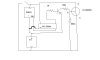
I have this pic circuit that i use to control a servo for 2 seconds. I press a momentary button and it powers up the pic and the transistor. The transistor powers up the mosfet. The pic chip keeps power on for 2 seconds and then shuts itself completely off.
Does anybody know a better way to do this without the transistor. Absolute zero current draw is a must.
 

Attachments

  • ZERO..JPG
    ZERO..JPG
    24.2 KB · Views: 244
Last edited:
Well, I didn't see any 12f684 around, but I'm assuming you're referring to a pic with nanowatt powerdown mode.

Simply:
* connect the PIC supply pins across the battery
* connect the switch from ground to an input pin that has an internal pullup enabled and that is capable of wake-up-on-pin-change
* connect an output pin from the PIC to the gate of the MOSFET (so no resistors or bjt required)

Program will be something like:

Code:
start:
   init all required uC peripherals -- including wake up on pin change and enabling weak pullups
   turn on MOSFET (& power to servo)
   do something with servo
   wait 2 seconds or whatever
   turn off MOSFET
   sleep  -- device uses ~ 400 nanoamps (ref 12F683 datasheet)
   goto start
 
Last edited:
I would do it this way (see attached). The only way to get zero current draw is to completely disconnect the input power. Relays are horrible components, but the only way to do this effectively. Everything semiconductor like will have a leakage current. The attached circuit is activated by a push button, the PIC then switches on the transistor, which energises a relay coil and the relay contacts bypass the push button, holding on the supply. When the PIC switches off the transistor, the contacts open and the circuit voltage collapses. The 1N4148 stops the back emf of the coil.

OK, relay coils take a lot of current to drive them, so you might be better off living with the leakage current of a FET (to replace the relay contacts) over a relay that needs lots of current to activate it. All this might be insignificant compared with the current needed to drive your load though...
 

Attachments

  • untitled..JPG
    untitled..JPG
    9.4 KB · Views: 160
Status
Not open for further replies.

Latest threads

New Articles From Microcontroller Tips

Back
Top