Continue to Site

Welcome to our site!

Electro Tech is an online community (with over 170,000 members) who enjoy talking about and building electronic circuits, projects and gadgets. To participate you need to register. Registration is free. Click here to register now.

  • Welcome to our site! Electro Tech is an online community (with over 170,000 members) who enjoy talking about and building electronic circuits, projects and gadgets. To participate you need to register. Registration is free. Click here to register now.

absolute value threshold detector thingy

Status
Not open for further replies.

throbscottle

Well-Known Member
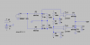
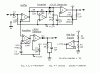
After spending far too many hours trying to cobble together an absolute value peak detector with a full wave precision rectifier, which would work up to 1MHz, I gave up on the precision rectifier part (which isn't really needed since I just want to detect input voltages over 1v ± peak) and did this way instead. One comparator is triggered if the input is over +1v, the other if it's under -1v. R1 would be adjustable in real life to set the threshold. I've tried simulating it down to 10Hz and up to 1MHz. The output is rather rough at low frequencies and the response time isn't very good, but it about does what I want it to do.

Can anyone help me improve it? I would like:
*Better symmetry when using real-world resistors
*Faster response to changes in input voltage
*Some proper hysteresis. Once the output has gone high, I don't want it to just follow the input when it drops a little. C5 provides the effect to some extent but real hysteresis would be better, since logic level output is lost when the input amplitude varies at 1 or 2 Hz - it needs to be immune to amplitude drops below the threshold down to about 0.5Hz. Increasing C5 makes the overall response too sluggish. Hope that doesn't sound contradictory!
*Neutralising the diode drops of D3 and D4 would be nice, but speed is more important.
*Not sure yet, this might actually need to be a window comparator

Thanks in advance, as always :)
 

Attachments

  • absolute-peak.asc
    2.9 KB · Views: 150
  • absolute-peak.png
    absolute-peak.png
    14.9 KB · Views: 248
Yep, I would go with the window comparator thingy. It should solve all of your problems.
 
Earlier today I realised this is actually a window comparator as it stands, but just not in the way I had in mind! But I'll look into it further, if indeed it will solve all my problems! (ALL of them, really? Woo Hoo! :) )
 
Okay, okay, maintaining tight symmetry might be an issue if you want to have an adjustable threshold AND some hysteresis. But other than that...:p
 
Last edited:
Thanks ronv - that's a really good replacement peak detector - I just need to make one for the negative half cycles! Can I ask how you arrived at the values for R1 and R2, and how you chose the schottky's, please?

As to what I am doing - I need to detect if a voltage is over +1v or under -1v peak to trigger a range up event on the dmm I'm still designing - hence the 2 comparators. ±1v peak is the maximum input for the rms converter to work accurately. Since the rms converter will give reasonably accurate results up to 1MHz, I might as well make everything else work up to that frequency. I was going to use simple one sided peak detection, but someone (I think it may have been you) pointed out that the negative and positive extents of a waveform are not necessarily equal.

I could also do with a <= 5mV detector to shut down the rms converter when the input drops that low, to stop erroneous results. So far in my scratchbook I have an amplifier with shutdown, with gain of 300, feeding a similar rectifier/comparator pair as in post #1. The amp is enabled by the output from the first detector being low, then when the output drops below 1.5v it can shut down the rms converter. Clunky but best I have so far and doesn't require a peak detector sensitive to 5mV.

Okay this is just thinking aloud now: If I've understood them correctly, maybe a log amp would be appropriate here, to compress the range? Instead of having a high level ±1v detector and an amplified ±5mV detector, everything would go though the same route, same peak detector. Something I need to investigate since I've only read briefly about log amps so don't really know anything.
 
I thought maybe you were using a signal generator or something like that so I just picked the 51 ohms. It also served to limit the current on the negative 1/2 cycle. The other resistor is just to limit the current for the op amp. Probably not needed since it is just a cycle or 2. I picked the BAT54 because they have almost no reverse current so don't discharge the cap when the comparator turns off.
Here is a circuit from LT that sounds like it would do what you want. They just used comparators, but after the RMS IC then logic to auto range.

https://www.electro-tech-online.com/custompdfs/2013/02/dn339f.pdf
 
My original idea a long time ago was to do the range switching based on the output of the rms converter (but not in the way described), which is a LTC1968, but it's input range is specified as between peak voltage limits rather than rms limits as for the LTC1966. After I discovered rms=pk*0.7071 is only true for sine waves, I decided to go for peak detection, hence messing about with peak detectors and comparators now. My adc has an over-range indicator (and I have a software under-range indicator) to control the switching, which would have worked very nicely otherwise with no extra parts :/

But thanks for that, it makes interesting reading - I had not thought about using a PGA. Something to think about for the mkII when it comes along.

Signal generator? 'Scuse me a minute, I'm going to roll around laughing and crying at the same time for a while... (Ahem) I don't even have anywhere to put one yet - be rest assured when I do (maybe in a month or too if I'm very good) I'll be building one. At the moment all I've got is an ancient (1970's) "Generatorscope" someone very kindly gave me, which combines signal generator of sorts with a 'scope of sorts in one case.

At least I'm somewhere near to having a decent multimeter now, homebrew as well, which is always good :D
 
Don't take my word for it, but I think the "crest factor" will compensate for your funny shaped signals. I don't know how but I guess I trust the data sheet. :eek:
 
Here is an alternative circuit, combining a 1V level detector with a <5mV detector.

As the requirement was for operation up to 1MHz, then a 10MHz quad opamp has been used for the amplifiers. A less capable dual amp has been used for the DC stuff. The circuit runs from a 5V single rail.

IC1 is used to obtain a half-rail supply for biasing of the amps. Ic2 is used as a buffer. IC3 inverts the incoming signal. D1 and D2 pass on the the positive and negative peaks to the detector IC4. Allowing for the voltage drop across the diodes, P1 will need to be set at around 350mV above half rail. R7 and R8 give a degree of positive feedback to give about 20mV hysteresis. R4 may need a few pfs across it to give compensation up to 1MHz for the input capacitance of IC3.

IC5 gives a gain of just over 210, so 5mV input will give 1.068V, and P2 needs to set to that value above half rail.

The circuit has not been tested or simulated, but should be a good starting point.
 

Attachments

  • AC Voltmeter.GIF
    AC Voltmeter.GIF
    7.7 KB · Views: 271
Far better than anything I was likely to come up with - thanks very much for that - single supply too - at this rate my split supply is going to become redundant! I will be firing up LTSpice shortly...

Can I ask why you chose the MCP6294 - was it just the gbw/quad combo, or what you happen to be familiar with, or were there other reasons? I ask because I'm still getting to grips with opamp selection, and going through the parametric searches of several manufacturers is quite tiring!

Very grateful :)
 
No, I haven't used it before. I saw you wanted to use it with the LTC1968, which operates with a 4.5V to 5.5V supply, so thought this circuit interface easily to it. You also wanted to measure signals up to 1MHz, so I Googled for '10mhz op amp single supply'.

Then I went through the list for various suppliers, and came up with that one by Microchip being sold at a reasonable price.

If you want any more details, then can you bear with me for a while? I am having an eye op on Friday, so I shall not be able to read for several days.
 
Oohya! Good luck with that eye op!

I'm just interested to know how other people select parts - I go on the "what's in my junk box or cheapest on eBay" method, but I now have some real (though still fairly approximate) parameters to use I can't realistically do that, so I was curious about

But your circuit is easily understandable, will do exactly what I want and easy to tweak if needed, and is better than my attempts, so I'll probably use it very nearly as is.
 
Status
Not open for further replies.

Latest threads

Back
Top