Continue to Site

Welcome to our site!

Electro Tech is an online community (with over 170,000 members) who enjoy talking about and building electronic circuits, projects and gadgets. To participate you need to register. Registration is free. Click here to register now.

  • Welcome to our site! Electro Tech is an online community (with over 170,000 members) who enjoy talking about and building electronic circuits, projects and gadgets. To participate you need to register. Registration is free. Click here to register now.

A simple qestion. Plese...

Status
Not open for further replies.

Someone Electro

New Member
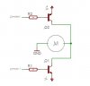
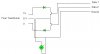
I need to control a smal motor with a output from a parallel port

i want just transistors no relays(just a smar motor: 100 mA)

PS:
The motor must be able to thurn in bouth directions
 
What voltage does the motor run on?

and what kind of power supply do you have available to drive it?
(voltage?, single or dual power supply?)

if a dual power supply is available then it's really simple...like this
(gnd switches a direction on; never drive both directions at once)
 

Attachments

  • Motor-L-R.JPG
    Motor-L-R.JPG
    14.3 KB · Views: 1,158
Its not a good idea to make parallel port sink the base current of upper PNP transistor. If base current is too high, it may blow up the port. Also the voltage +V has direct effect on base, which when greater than 5V has potential to destroy the port.

So use additional NPN transistor to drive PNP. Drive this NPN with parallel port.
 
One should always buffer the parallel port (with an 7407 and pullups for example).
Forgot to mention that idd
 
a 6 transistor H birdge can do the job for a single suply.
specialized ics can be found for this to....a more elegant solution.
 
kinjalgp said:
Its not a good idea to make parallel port sink the base current of upper PNP transistor. If base current is too high, it may blow up the port. Also the voltage +V has direct effect on base, which when greater than 5V has potential to destroy the port.

So use additional NPN transistor to drive PNP. Drive this NPN with parallel port.
Also, the NPN in the schematic (with emitter to V-) can't be turned off with TTL logic levels. You would need a PNP to drive this transistor.
 
Yes RonH, I forgot to see that part of the schematic.
 
Also, the NPN in the schematic (with emitter to V-) can't be turned off with TTL logic levels. You would need a PNP to drive this transistor.

The problem is not with the NPN transistor, its with the PNP. Ive built circuits with the parallel port using NPN transistors and they worked fine. A high output on a parallel port pin will turn an NPN transistor ON a low will turn it OFF. If you want to insure that the transistor is OFF ,during a low , simply connect a 10K or so resistor between the base and ground.

An even better idea when working with the parallel port is to use an opto isolator IC such as a 4N25 to drive the transistor. This will give perfect separation between the computer parallel port and any connected loads especially motors and relay.

Heres a link that explains this in more detail.

http://www.hut.fi/Misc/Electronics/circuits/parallel_output.html
 
I have a transformer that has three wires out: 0V , 6V and 12V

And i had a idea:
The uper shematicks can use a litle power suply changes!
V+ and V- can be the 6V on the transformer(with a diode to set polartivity)
The GND can be the 0V with the Ground on the parallel port

Can it work? :?

I know the motor will be a litle buzzy

PS:
I dont have a power suply like that so i will use a transformer!
 
nettron1000 said:
Also, the NPN in the schematic (with emitter to V-) can't be turned off with TTL logic levels. You would need a PNP to drive this transistor.

The problem is not with the NPN transistor, its with the PNP. Ive built circuits with the parallel port using NPN transistors and they worked fine. A high output on a parallel port pin will turn an NPN transistor ON a low will turn it OFF.

Nettron, you can switch an NPN with the parallel port if the emitter is grounded. Look at the schematic. The emitter is connected to V-. If you ground the base, the base-emitter junction is still forward-biased. You need a PNP as a level translator.
I agree with your suggestion to use optoisolators for motor control.
 
Nettron, you can switch an NPN with the parallel port if the emitter is grounded. Look at the schematic. The emitter is connected to V-.

Doh! hadnt noticed thats a dual polarity power supply.

But i'd caution against using PNP transistors on the parallel port. As Kinjalgp already mentioned the port would have to sink current to ground, ive bin warned by others , when i was working on my circuits , not to use PNP transistors.

Actually i later decided to go with a ULN2803 darlington transistor array IC to drive loads using the pararllel port.

Ive posted a schematic of my design in the Robotics chat forum of this board, if anyones interested.

https://www.electro-tech-online.com...-series-eprom-to-a-2-wire-serial-eeprom.3019/
 
I just cant get it to work!!! :x :x :x

Im desineing the circuit in Crocodile Tehnology!

I just got the 4 transistor circuit to work but i want to have it with yust 2!

if i use the 4 transistor i need 16 transistors for 4 motors!!!
And thats lo lo!

PS: the 4 transistor can work with a normal batery
 
Why don't you go in for L293 H-bridge ICs? You'll only require two of these ICs and each can deliver 1A current to the motor. And it has TTL compatible control inputs so you don't have to worry about interfacing it with the parallel port.
 
After some time of mesing with the simulator i finaly got it! 8)

This is made of just 2 diodes, 2 transistors and a transformer!

Dose it realy work or is just a bug in the simulator? :?


What do you have to say?Do you like it? 8) 8) 8)
 

Attachments

  • Motor_Control.jpg
    Motor_Control.jpg
    15 KB · Views: 987
hmmm dual supply... interesting.....
 
The top transistor will work as an emitter follower, so the voltage across the motor will never be more than the voltage on Data 1, minus the Vbe (0.7v) of that transistor. The bottom transistor will never switch the motor. What simulator are you using? Given your level of knowledge, I'd be more inclined to say it's a bug in the operator. :roll: I don't mean this as a put-down. It's just a fact that a simulator in the hands of an inexperienced person can give misleading results. In fact, a simulator in the hands of an experienced person can give misleading results, and the simulator is generally not the problem. I'm not putting down simulators - I spend most of my time at work using Hspice and Agilent ADS. I use Linear Technology's free SwitcherCAD III at home. This experience has led me to these conclusions.
 
I use the "Crocodile Technology" Simulator.

Its a demo so i can't save circuit's but i am working a program to save the copy'd file from the clipboard and then paste it in agen!(Its Save/Load my stile 8) )
 
In the negative side You need a PNP transistor. I recommend to use darlingtons.
 

Attachments

  • Motor_Control_196.jpg
    Motor_Control_196.jpg
    11.7 KB · Views: 400
Status
Not open for further replies.

Latest threads

New Articles From Microcontroller Tips

Back
Top