Continue to Site

Welcome to our site!

Electro Tech is an online community (with over 170,000 members) who enjoy talking about and building electronic circuits, projects and gadgets. To participate you need to register. Registration is free. Click here to register now.

  • Welcome to our site! Electro Tech is an online community (with over 170,000 members) who enjoy talking about and building electronic circuits, projects and gadgets. To participate you need to register. Registration is free. Click here to register now.

A little help please

Status
Not open for further replies.
remember that the circuit I posted may not be correct but its a start.
looking at the circuit several times I see there are minor problems.
but its a start
 
Maybe a silly question but i suppose i have to learn, what are the circles with + and - in at v3, v2 etc. I understand v1 is LDR.
 
Copied what I could into ltspice and this is what i have upto now, i edited resistor value to 220ohm but dont know what the boxes around red exit, flash etc mean or how to put them in. I presume they are inputs/outputs from somewhere else?

62-light1.png
 
new plan

this circuit works it appears.
If you send me your Email I can Email you the lt spice file. then you don't need to redraw and maybe end up with mistakes.
attached is new revised schematic.
this uses NAND and AND gates as well as 3 input NOR gate.
you will need to condition the switch inputs so some Schmitt trigger 7404's should work to invert A3 & A9.
 

Attachments

  • slotcar2.PNG
    slotcar2.PNG
    36.9 KB · Views: 250
Thanks for the reply, just one question; could pit open led and exit open led be run from a6 instead of having a2 purely for exit open light or have i overlooked something. im only saying this as both green led are lit at same time
 
Ok ive been looking at the graphs in ltspice and can see what each stage looks like. Im a little confused as to what the "flash" arrows are for and the power supply for them in top left corner.
Ive been looking at schmitt triggers and there are a few options in ltspice, which do i use? are a8 and a7 the 556 timer you mentioned? apologies for so many questions but i dont know anyone who local who is knowledgeable on this type of subject.
 
in your want list you have pit open & exit open in stage 1 but pit open = off and pit exit = on n stage 3.
and in stage 2 & 3 pit open is off and pit exit is on.
so the answer to your question is no. Leave A2 in circuit
an inverter in place of the NAND gate but need to count up the number of NAND gates Usually 4 to a chip (74ls00)
question = battery or wall wart power supply?
 
Apologies, getting confused with when the light was on/off youre right and is correct as it is. This will be mains powered. Could the output on pit open led also be used to control a servo/flipper on the track to prevent car 2 entering pit while car one is pitting?
 
Last edited:
schematic file

YES you could control a flipper using a servo. Need specs.
Assuming you are building using TTL? If you wanted you could build with CMOS, just be aware of handling precautions.
You also need to build an adequate power supply
add up all the IC current draws plus the 20ma per LED plus what ever the servo draws then double the amount needed. suggest using LS if going TTL (74LS74 etc)
I like to be sure
7474 = 17ma
7414 = 30ma adverage
7403 = 8ma adverage
8 LEDs = 160ma
7490 = 32ma
555 = look it up
current draw adds up quick!
suggest a simple 7805 with a 9v wall wart sounds good but ??slotcar3.PNG
 
il find a servo or evivalent that i can use and post the spec. I understand and/or etc but cmos and ttl dont mean much to me. Can you explain a little deeper. I googled ttl and came up as transistor transistor logic, which i assume is just a logic gate on its own and not part of an ic where as cmos is?

As for power supply can i use a standard adaptor such as: **broken link removed**
 
Last edited:
Those are ok but a DIY power supply would be cheaper and maybe better depending on how you build it.
If you never worked with IC's before then the TTL is probally a better choice. The major difference is cmos uses less current and has a wider voltage requirement. Where as TTL must have a well regulated 5volt power supply and well filtered. There are numerious sources on the web for schematics.
Now about that flipper/servo thing. IMO you would be better isolating a section of track at the pit entrance.
EXAMPLE = a 12inch section of track with one of the tracks 2 metal rails cut, thus isolatng from rest of track. when the pit closed LED comes on that isolated section goes dead thus eliminating any cars from enterng the pit.Section goes live upon the pit open LED coming on.
This section is switched using a simple transistor depending on current demand. Much simpler than usng a servo that may need PWM to control it (whole other ball game)
The FLASH arrows are to show that that connection is connected in the circuit where any other arrow with FLASH inside it. The boxes around pit exit etc. indicate test points.
Tune on LT SPICE and probe a test point wire and the graph will indicate the test point.
Dd you get the revised schematic (PCExpress file?) as well as the LT SPICE FILE?
 
lt explained

here is a brief explaniation of whats going on.
as a suggestion, load one of the sample circuits in LT SPICE or load the file I emailed you (easire to configure real simple circuits to get your feet wet first)
probe around, play with the circuit etc. LEARN while doing.ltspice explain.PNG
 
Thanks for the replies, i think id better explain a little about the track system in use as it concerns how the track is powered.

Im going to be using scalextric digital system and a new power module (c7042) is due for release soon and i dont know if changes to the power rails will interfere with the digital system and how it records information.

If i could keep all my ideas together on a separate stand alone system i know no problems would be encountered. It had crossed my mind to take the power supply for my system directly from the track.

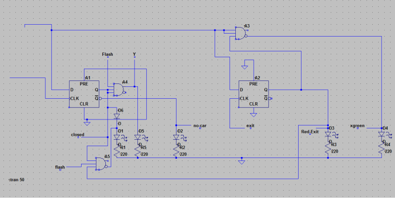
If part of one lane loses power when car 2 reaches dead strip area while car 1 pits, car 2 will stop.

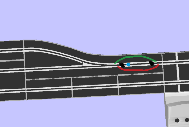
So i thought by using a little servo to move a home made flipper i could prevent car 2 from entering pit by redirecting the car so it would avoid the scalextric pit sensor all together.

75-pitedit3lane.jpg


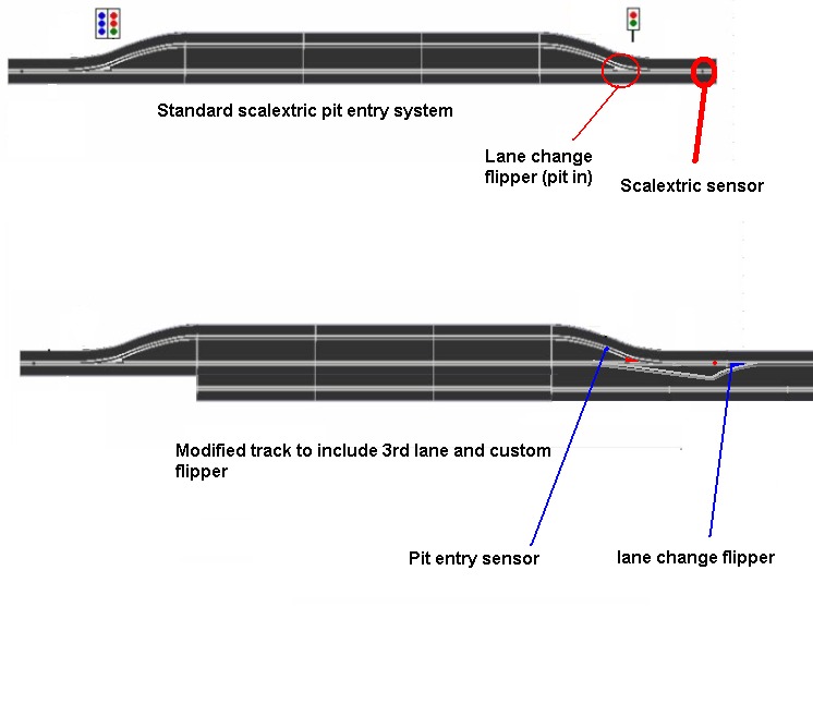
top pic is out of the box track

bottom pic is how id modify track (roughly, quick sketch);
car enters pit as normal and activates my pit in sensor and moves flipper to divert any following cars around scalextric pit in sensor. this would also act to improve close racing of cars and people would have to avoid car/take caution incase someone decides to pit. the car could even be diverted to the other lane.

I havent got any more files in my inbox and im getting used to using pcexpress and ltspice, im gettting my head around it all but its just information overload at the minute lol.

Again thanks for all your help so far.
 
Last edited:
did you get the pc express file? as I sent it late Friday nite or there abouts (within the last 48 hours.
I also sent the revised LT Spice file.
 
scalextric is same as DCC

modle rail road digital control.
simple matter to isolate one rail.
just set up track in circle and leave one section out. setup should still run cars.
here is what I am suggesting.track isolation.PNG
 
I think i get what you mean now, are you on about isolating the scalextric sensor and flipper from the rest of the track so those components would not function while a car is pitting?

77-pitcutpower-1.png


So this would create a dead strip and isolate scalextric pit in sensor (blue dot) that would normally activate flipper.

checked my inbox again and i do have slotcarsch file, thanks.
 
Last edited:
YES it would creat a dead section. If a car tried to pit while another car is present then that car is disabled until the open pit led comes on. Kind of a penatly on not paying attention to the pit lighs. I see there is a SCALEXTRIC pit game addition that lets the "driver" know how many pit stops they have made. At least thats what I understand.
This pit light setup along with the pit game track section could make for some exciting racing.
will resent files.
 
Got files now thanks, email just popped up. Youre right about the pit lane game from scalextric and it will be added to my track albeit with a few minor alterations. The only problem i have with a car being stopped waiting to pit is that it ties up that lane until the car can enter the pit. I like the suggestion but i can see expensive slot cars ending up in lots of bits if a driver is not paying attention. If i isolated a section just big enough to cut power to sensor and flipper the cars momentum would take it across that area allowing it to continue on the lap
 
I got some info on the scalexy pit in system and the flipper will be left directing cars into pit (from car A going into pit) until car B crosses sensor and changes flipper back to straight ahead posistion so my idea reverts to adding my own lane change before scalextric sensor
 
Last edited:
Status
Not open for further replies.

New Articles From Microcontroller Tips

Back
Top