Continue to Site

Welcome to our site!

Electro Tech is an online community (with over 170,000 members) who enjoy talking about and building electronic circuits, projects and gadgets. To participate you need to register. Registration is free. Click here to register now.

  • Welcome to our site! Electro Tech is an online community (with over 170,000 members) who enjoy talking about and building electronic circuits, projects and gadgets. To participate you need to register. Registration is free. Click here to register now.

A little help please

Status
Not open for further replies.

kris8583

New Member
Hi all, im please I found this place I could do with some help.

Id like to design a little led circuit for my scalextric pit lane that is activate when a car enters the pits.
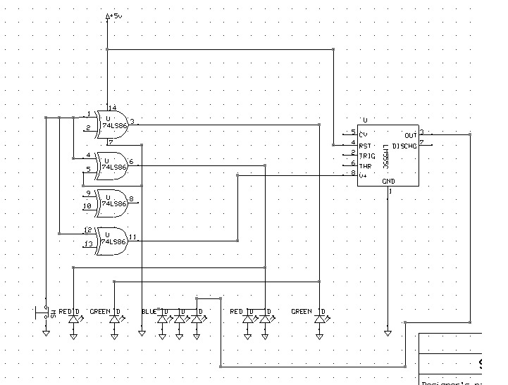
Here is what id like to do:

10-picpitlane.jpg


For now ignore the track flipper section, all i want is the lighting circuit activated by a car driving over a switch or sensor and reset when it leaves the pit.

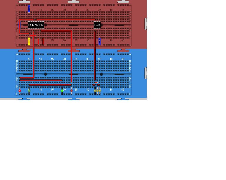
Ive been using a java online breadboard but not had much luck myself. All help is greatly appreciated. Any questions please ask.
 
your description is a little hard to understand?

From what I understand is
This is a slot car track?
When car is in pits you want a red LED on
When pit is empty green LED on
If pit is closed a flashing LED

This circuit sonds very much like the model railroad circuit I and several other members have been working on.
Let me find the post and circuit link
will get back to you
 
here is the basic circuit. just need to add a flashing LED
circuit is pretty simple

**broken link removed**
 
Thanks for the reply.
No car in pits = GREEN LED entry ON, GREEN LED exit ON
Car drives over switch/sensor and enters pit lane = GREEN LED entry OFF, RED LED entry ON and flash, BLUE LED ON and flash, GREEN exit OFF
Car drives over switch sensor at end of pit = RED LED entry ON and continues flashing 10 Seconds, BLUE LED OFF, RED EXIT LED ON and flash 10 seconds
Car now totally clear of pit, after 10 second flashing system reset.

Hope that makes it a little clearer, il have a look at the link and see if i can make sense of it lol.

what type of switch/sensor would i use? I wanted to fix a switch under the slot the car guide blade sits in so it pushes the switch closed when it passes over it.
 
20-pit11.png


Thats as far as i got, got the basic bits done and need to add leds for red exit light but thats simple enough job. could someone please help finish it off?
 
Last edited:
If you want help then draw an actual schematic using a schematic drawing program or draw one but make it very clear what you have.
the breadboard pic dosn't tell me anything except you have a 7408 and a clk???
if you use the schematic in the link I posted you will see how it works. breadboard it then run try it out.
the flashing led is a minor issue. WHAT EXACTLY do you want to happen??
 
Thanks for the reply. I have never used a schematic drawing program before so i will have a go and see what i can do. I have only a little knowledge on building circuits so please be patient with me.
 
curious what or where did you get the idea to use the 7486 and a 555? timer for clk.
f you can explain clearly what you want the circuit to do?
green = pit open
yellow = pit is busy
red = pit is full
how many cars etc??
 
1 car at a time. your correct with the lights for each type. 7486 and clk were just what i stumbled across and seemed quite easy to get to grips with. Ive been told i could program a pic but seems a little advanced for me. I think i need a switch at each end of pit lane so it knows a car has entered then left. when sensor 1 at start of pit is activated light change from green to red/yellow as per table above. once car leaves sensor 2 is activated resetting system and putting green lights back on.

i can do another table showing what is on off in each step of pit entry/exit if required to make it easier to understand
 
Last edited:
Lets try your new table
Is this slot cars or remote control.
What kind of car?, how big as what type of sensor is needed?
 
Ok heres the new table hope it makes things a bit clearer. (yellow led changed to blue)

40-pittrut.png


This is for scalextric slot car system custom setup.

All cars are basically the same and i wanted to put switch under the track so the guide blade of the car catches it as it passes over it.

I was thinking of using a switch (see link) so the car guide can brush past it and send signal as required
**broken link removed**

Hopefully things are becomming clearer lol, thanks for your hep so far
 
Last edited:
alot clearer now.
The name sounds similar to a slot car set I had when I was in 6th grade ELDON SELECTRIC slot car set.
instead of contact micro switches which could make the car bounce from the track, use a phototransistor embedded in the track. car passes over and triggers the circuit.
this would be really easy using a PIC (micro controller) but seeing how your not equipted to do it we will try a simple circuit using discrete components.
is this for one car or multiple cars same lane or different lanes?
Does the car need to stop for X amount of time in the pits? or just drive in then out?
 
I could use phototransistor instead but dont think that microswitch would interfere too much with the car. i had a look at one in maplin and it didnt offer much resistance when pressed, and id like to hide as many components as i can under the track. I would mount the switch under the track on its side to minimise inteference with the car.

Ive been reading about pic programming and looked at mplab and would like to get to know more before i start on something that difficult lol

All cars (up to 4) would be racing at the same time using all lanes, in my picture above with the scalextric track there is a table column, pit lane in flipper, this would be added to prevent other cars entering pit once one had entered by moving the flipper to a "no entry" posistion. I could use an empty input/output on the chip to send a signal to a little servo to pull the lane closed.

The cars will, for now just drive through, i can add resistance to the section of the track in the pit to reduce speed and slow the cars down, then they resume full speed on leaving. In the future id like to add other elements to the pit and other areas of the track but want to learn to walk before i can run!
 
here is a start

this is simulated in LT SPICE
the FLASH is a 556 (2x 555 in one) wired as a monostable and astable timers.
the mono is connected for 10 seconds and the astable is running at 1 pulse per second (1hz)
**broken link removed**
If you could download LT SPICE and run same simulation you will get a better grasp on whats happening. This way you will learn as you build.
A NAND gate should be added to reset the first Dflip flop.
If battery operated then cmos IC's
time to do some homework but this schematic should get you going.
suggest breadboarding first and observe input requrements =(no floating inputs)
 

Attachments

  • slotcar.PNG
    slotcar.PNG
    49.2 KB · Views: 170
simple alternative to AND gates

yopu could just use diodes for the AND gates instead of IC's
 

Attachments

  • and gate.PNG
    and gate.PNG
    29.7 KB · Views: 155
Thank you ever so much for the schematic. I havent had time yet to have too much of a look at the schematic. Some of the component pics im not too sure on but ive only just started with electrics so ill do a bit of research and get more familiar with it. Am i ok to come back to you with any questions i may have or advice i require?

Just out of curiosity, how ok was my schematic for a first attempt, am i along the right lines with it?

thanks again, regards Kris
 
Last edited:
Your schematic was in the ball park as it wasn't hand drawen. The basic schematic I posted was just that, basic,
It needs work and an actual schematic drawen using an actual schematic drawing program like express pcb. which your schematic looks like it was drawen using?
the drawing I posted is a screen shot of LT SPICE. It needs a monostable timer on the last D flip flop to reset the first D flip flop so the green pit open LED comes on.
will draw up tomorrow Saturday morn.
In the mean ime, perhaps download LT SPICE to simulate this circuit at this point. If your not careful you might learn something.
 
Youre correct it was drawn with express pcb. Il download LT Spice and have a play while im at work tonight. Thank you ever so much once again
 
Status
Not open for further replies.

Latest threads

New Articles From Microcontroller Tips

Back
Top