Continue to Site

Welcome to our site!

Electro Tech is an online community (with over 170,000 members) who enjoy talking about and building electronic circuits, projects and gadgets. To participate you need to register. Registration is free. Click here to register now.

  • Welcome to our site! Electro Tech is an online community (with over 170,000 members) who enjoy talking about and building electronic circuits, projects and gadgets. To participate you need to register. Registration is free. Click here to register now.

a little help needed

Status
Not open for further replies.

sleepwalker

New Member
hello friends, this is my first post.

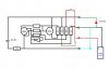
i need help on my solar project on which the photo sensor is no longer needed.

the schematic diagram i get from existing pcb, and i did my best to draw it even if i don't understand them at all.

which parts on this schematic diagram should i eliminate? ( in order not to use the photo sensor anymore).

how could the solar panel charge the battery? (which circuit it uses), and which circuit is use to light the LED?

thank you.
 

Attachments

  • schematic solar vest.JPG
    schematic solar vest.JPG
    41.2 KB · Views: 136
Last edited:
What kind of photo sensor is it? I'm assuming Cadmium sulfide as those are common on small solar setups like that. You can tell if it's a CDS cell by looking at it, they tend to look like an S or grid pattern through the window. If you want to fake it into thinking light is always shining on it, remove the photo resistor itself and replace it with a low value resistor, perhaps 10 ohms or lower. If you want to fake it into thinking it never has light being shone on it you can simple remove the CDS cell and replace it with a high ohm resistor, perhaps 1meg. For always 'off' simply removing the photoresistor and putting nothing in it's place may work.
 
thank you Sceadwian.

yes, it is a photo sensor use for solar panel.

i need to redesign the circuit so i can produce more than 5,000 pcs of it for solar vest (with flashing LED ) use by traffic security and road workers.

what else should i remove from the circuit? (semi conductors).
 
How long will a fully charged battery light the LED?
Will the battery fully charge in one sunny day?
How will you charge the batteries on cloudy days?
 
I personally think solar powered lawn lights are simply gods way of saying, here electronics geeks, have some bits to play with. All serious consistent lightning schemes are going to use mains power. The CDS cells in there are fun to play with, the device probably costs less than the batteries that were in it, and the solar cell is just a bonus.
 
the solar panel costs US$0.60 each, Peak Voltage (Vmp):3.5V, Open Circuit Voltage (Voc): 3.5V-4.0V, Peak Current (Imp):45mA, Short Circuit current (Isc):45mA-48.5mA.

the battery cost more, US$4.50 for Li-Po battery pack. but i might just use Li-ion which cost about US$0.67 per pack.

anyway, i have fix the schematic diagram since the other terminal of the sensor was not indicated.

i want to have another factory fabricate the pcb and need to remove the sensor function. can please help me?
 
Status
Not open for further replies.

Latest threads

Back
Top