MrDEB
Well-Known Member
Pulsing w/ 60ma
not 120ma
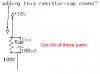
maybe by puting in parallel ??
with 64 leds total I wonder if the viewing angle really matters?
the arrays are on 1/2" wide - 8 seperate boards to fit into a 2" round tube
shall we say high density.
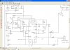
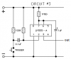
question is will the 7556 drive the 8 darlingtoin transistors and the piezo unit.
another item I need to consider will a 50ms pulse allow the leds to achieve full brightness.
the triggering of the 7556 needs a low signal. If the signal stays low will the circuit continue to keep triggering? or will it cease after one cycle./
not 120ma
maybe by puting in parallel ??
with 64 leds total I wonder if the viewing angle really matters?
the arrays are on 1/2" wide - 8 seperate boards to fit into a 2" round tube
shall we say high density.
question is will the 7556 drive the 8 darlingtoin transistors and the piezo unit.
another item I need to consider will a 50ms pulse allow the leds to achieve full brightness.
the triggering of the 7556 needs a low signal. If the signal stays low will the circuit continue to keep triggering? or will it cease after one cycle./