Continue to Site

Welcome to our site!

Electro Tech is an online community (with over 170,000 members) who enjoy talking about and building electronic circuits, projects and gadgets. To participate you need to register. Registration is free. Click here to register now.

  • Welcome to our site! Electro Tech is an online community (with over 170,000 members) who enjoy talking about and building electronic circuits, projects and gadgets. To participate you need to register. Registration is free. Click here to register now.

8 transistors = 1 tip120?

Status
Not open for further replies.

MrDEB

Well-Known Member
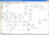
In this project I need more pcboard real estate. The tip120 takes up too much room.
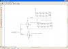
Thought about using 8 - 2n2222 transistors in parallel.
according to calcs?? one - 4 led array = 450ohms
the 2n2222 = Ic = 800ma, beta = 75
the circuit -- Vcc = 18v
Load = 450 ohms
base voltage = 1v
emitter current = 300mv
running each array at 30ma
the 7556 has an output current of 50ma
Just never saw transistors in parallel??
note - the circuit has 8 - 1/2" x 4" boards. thinking of putting each 2n2222 on each board and large traces for power and ground between boards.
using **broken link removed** for transistor simulation
each LED as of right now (looking at using SMD LEDs) 3.4 voltage drop (white)and running at 30ma (might increase as only flashing at 50ms.
 

Attachments

  • Capture2-9-2009-7.29.31 AM2-14-2009-2.30.40 PM.jpg
    Capture2-9-2009-7.29.31 AM2-14-2009-2.30.40 PM.jpg
    173.4 KB · Views: 407
Here we go again and again.
Why post another thread?
Will each 2N2222 drive 8 strings and have a collector current of 400mA? Your schematic says 16-3 and 50mA. But you say 30mA???? Then each transistor drives 240mA?
What is 450 ohms? Why does the schematic show 100 ohms that limits the current to 44mA?

Paralleled transistors do not equally share the base current. One might take most of the current leaving not enough base current for the others. So each transistor needs its own base resistor.

The piezo buzzer will not make any sound because the base-emitter of the transistors limits its voltage to about only 0.8V. If a single transistor is used then the 7556 doesn't have enough output current to also drive the buzzer.

The transistor is not a linear amplifier with a collector to emitter voltage of 10V when it is conducting that uses BETA in its base current calculation. Instead your transistors must saturate in order to turn on the LEDs. The saturation spec in the datasheet for most transistors is with the base current 1/10th the collector current, nothing to do with BETA.

The 7556 is Cmos and has a low output current. With a 12V supply its max output high current is only 10mA (not 50mA which is when its output is low) when its output voltage loss is 1.5V. So the 1k base resistor provides a base current to the transistors of 10mA. It can drive only a single 2N2222 and the output current of the 2N2222 will be only 100mA.
That is why a darlington transistor was selected in the other thread.
 
Trying to come up with more

I am hoping to eliminate the tip120 and go with small transistors on each led array board.
If I put 2 transistors in a darlington pair connected to the 7556 output then turn on the 8 transistors??
didn't know if connecting 8 transistors in parallel make a difference?
will reconfigure with home brew darlington??
got to be a solution??
 
I see they make to92 darlington transistors

just what specs to look for
gain, etc. to turn on 8 transistors with the led arrays?
 
If each transistor has a load of 240mA then each base current is 24mA and eight of them is a total base current of 192mA. Use a darlington transistor to drive them, each with its own base resistor. The 7556 can drive the darlington with only 0.8mA and the piezo buzzer can get the remainder of its 10mA.

For a transistor to turn on then you look for its Max Saturation Voltage Loss where its base current is 1/10th its collector current.
 
Last edited:
This 1a darlington fit the bill?

MPSW45AG

have this on the 7556 output as well as each array?
looking at some 350ma leds but run at 200ma.
**broken link removed**
 
The 1A darlington can have a load of 1A only when it has some kind of heatsink.
It is almost impossible to heatsink it. If its saturation voltage is 1.5V then its current must be no more than 667mA and at its max allowed temperature it will be extremely hot.

The high power LEDs look like they need a "metal-core" pcb to cool them.
Instead, buy Luxeon LEDs that can be bolted to a heatsink.
 
confirm calcs

leds=3.4 forward voltage, 60 ma
Vcc = 18v,
4 leds in series = 13.6v drop
4.4/.60= 150ohm load
transistor 75 beta (2n2222)
load 150ohn (4 led and one 73ohm resistor)
Cv=1
Bv = 1
Ve =300mv
Ic = 113ma


put 8 leds (2 - 4 led arrays(w/ 73ohm series resistor as above) in parallel = 75ohm load 226.67 ma
plan is to turn on the 8 - 2n2222 with one darlington connected to the output of a 7556
diagram following
 
couldn't figure out where to put 2n2222

figure this might work as well?
Just added additional 1K resistors from 7556 output???
hope this looks good???
 

Attachments

  • Capture2-9-2009-7.29.31 AM2-14-2009-8.36.23 PM.jpg
    Capture2-9-2009-7.29.31 AM2-14-2009-8.36.23 PM.jpg
    101 KB · Views: 249
leds=3.4 forward voltage, 60 ma
What is the max allowed continuous current for ther LEDs? 60mA seems to be too high.
Look on their datasheet to see if they can be pulsed at 100us without melting.
My Fairchild red LEDs are rated at 40mA continuously or 200mA for 100us. 50ms is 500 times longer.

Vcc = 18v,
4 leds in series = 13.6v drop
4.4/.60= 150ohm load
60mA is not 0.6A.
4.4V/60mA= 73.3 ohms, not 150 ohms.


transistor 75 beta (2n2222)
Beta is not used for a saturated switching transistor. The base current must be 1/10th the collector current.

load 150ohn (4 led and one 73ohm resistor)
What is 150 ohms?

Cv=1
Bv = 1
Ve =300mv
Ic = 113ma
What is this all about?

put 8 leds (2 - 4 led arrays(w/ 73ohm series resistor as above) in parallel = 75ohm load 226.67 ma
No.
The current in each string is 60mA so two strings have a total current of 120mA.
What is 75 ohms?

EDIT:
Your latest schematic does not have any supply voltages so it is meaningless.
 
Last edited:
Of course you can use the gain of a transistor when it is in saturation mode. Most small-signal transistors have a gain of at least 100, so 1mA into the base will deliver 100mA via the collector-emitter circuit and have the transistor fully saturated.
A 2N2222 will pass 500mA via the collector-emitter circuit so that this transistor will be suitable for the application.

The 7555 will deliver 100mA output current at 18v so you don't have any problems connecting the driver transistor to the chip via a 1k resistor.

The only unknown factor is the dropper resistor for the string of LEDs. The value will depend on the number of LEDs in the string and the colour of the LEDs.
Allow 1.7v for red, 2.2v for green and 3.6v for white.
Allow 20mA for each string.
Search the web for a calculator to determine the value of resistance for the dropper resistor (also known as the current limiting resistor).
Or take the total LED voltage from 18v and get an answer.
Divide this answer by 0.02 and the result is the dropper resistance in ohms.

Colin Mitchell
TALKING ELECTRONICS.COM
 
The 2N2222A (PN2222A) does NOT have a gain of at least 100 in saturation with a 500 mA collector current. The ONsemi data sheet shows that the gain is typically 50 and is only guaranteed to be 10.
 
I did not say the transistor would have a gain of 100 when passing 500mA.

I said the transistor is capable of passing 500mA so it would be suitable for the application.
Furthermore the current for this application is about 150mA and the gain for the transistor is about 30 to 50 at this current-flow, as stated in the application notes. And these are minimum values.

Colin Mitchell
 
Last edited by a moderator:
Have you considered using a logic level input N-Channel MOSFET as a sinking driver?

For example, the 20 volt 5 amp Vishay **broken link removed** has a very low Rds(on) resistance (0.031 ohms at Vgs = 4.5v ... 0.047 ohms at Vgs = 1.8v) and is available in a relatively small SOT-23 package.
 
LEDs I am planning on using

found these on Ebay. Similar here in states are $7 each they have 3 chips. only going to flash once for 50ms. so heat shouldn't be a problem
**broken link removed**
the LED resistor calculator -
LED Resistor Calculator

transistor cal but it dosn't do darlingtons
**broken link removed**

the 150 ohms = I was trying to compute the resistance of the LED string/ resistor array then divide in half as I am putting 2 arrays in parallel
don't know where I got sidetracked??
E=18, I=.060 (60ma?) R= 300 /2 =150
not real sharp on math but I try.
so if my collector current is 120ma the base current must be 12ma?
the 7556 only delivers 100ma output so what does the darlington need if I put 8 in parallel and still operate the piezo?
 
Of course you can use the gain of a transistor when it is in saturation mode. Most small-signal transistors have a gain of at least 100, so 1mA into the base will deliver 100mA via the collector-emitter circuit and have the transistor fully saturated.
Not true.
The datasheet of most transistors shows the max saturation voltage loss when its base current is 1/10th the collector current. Small very high gain transistors list their saturation voltage loss when the base current is 1/20th the collector current. The 2N2222 and 2N2222A transistors list their max saturation voltage loss when the base current is 1/10th the collector current.

The 7555 will deliver 100mA output current at 18v so you don't have any problems connecting the driver transistor to the chip via a 1k resistor.
Not true.
The Intersil datasheet shows that its absolute max supply voltage is 18V but most spec's are from 3V to 16V.
A curve of its "typical" output high current shows it delivering a max of 50mA into a dead short and only 7mA when it has a 1V loss. Its output low current is much higher.
The LMC555 has an absolute max allowed supply voltage of 15V and the saturation voltage loss is a max of 1.5V when its output high current is only 10mA and the supply is 12V like it is in this project.
The TLC555 has a max supply voltage of 18V but a max of 15V is recommended. Its saturation voltage loss is a max of 2.5V when its output high current is only 10mA and the supply is 15V.
 
The absolute max allowed peak current in the tiny Chinese LEDs is 100mA and you are going to feed pulses of 120mA? Then you will kiss them goodbye.
I wonder why they do not list the viewing angle? Maybe it is extremely narrow?
 
Status
Not open for further replies.

Latest threads

New Articles From Microcontroller Tips

Back
Top