Continue to Site

Welcome to our site!

Electro Tech is an online community (with over 170,000 members) who enjoy talking about and building electronic circuits, projects and gadgets. To participate you need to register. Registration is free. Click here to register now.

  • Welcome to our site! Electro Tech is an online community (with over 170,000 members) who enjoy talking about and building electronic circuits, projects and gadgets. To participate you need to register. Registration is free. Click here to register now.

74HC595 Shift Register with 4 Dig Com Anode 7 segment display

Status
Not open for further replies.

Mosaic

Well-Known Member
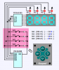
Here is a complete Proteus sim with asm code running a number of useful routines.

1) A simple debouncer in asm, easily understood, not as eff. as a parallel debouncer.
2) Binary to decimal conversion for counting.
3) 7 segment lookup table to display digits.
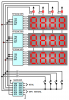
4) Shift register serial data transfer with column select and strobe for each digit.
5) ASM delay in main loop to effect a precise strobe time, as opposed to an interrupt.
6) Sampling of a couple tactile switches.

Almost every line is commented.

I used a 16f886 which I find to be a very flexible chip, although there are better ones now.

Clicking Sw1 counts up, Sw2 reset the count.
You can swap in other Shift registers, just keep track of the pinouts as they are not necessarily pin for pin replacements. The TPIC6C595 Shift reg. packs a lot more power and can drive LEDS quite bright which is necessary when strobing for best effect.

Change the 'bin' extension to DSN to use in Proteus.
 
Colin:
The hex gate is just for the simple functioning of ISIS....if u look at the bitmap pic u see that it is indicated that the gates will be replaced by PNP or P channel transistors. ISIS had sim probs with the actual transistors.
 
I use the 16F886 and the F887 extensively. The F886 fit into the design and PCB layout of my MIDI controller pedals quite nicely. Very nice PIC to work with.
 
Update

Here is a somewhat improved version of this topic.

The asm code is cleaned up and commented to enable the user to easily switch between 2 or 4 digit, CC or CA displays and also use tactile switches running off the column select lines to minimise pin usage.

The new schematic is also posted as a BIN file, rename to DSN extension for Proteus.

The switch sampling GPR etc will dovetail with my other post on parallel debouncing for handling multiple switches efficiently.

The final improvement makes it simple to use any Dig. output pin in any port for the Shift Register and column select and switch I/O. Mix and match pins and ports freely now. This will make it easier to layout a congested PCB or work with MCU firmware that has only scattered free pins available.
 
Last edited:
Your method looks remarkably similar to one of my MacMux designs from long ago (below) except you haven't implemented the PWM brightness control.

The MacMux design is relatively flexible and expandable. You can use NPN or NFET drivers for CC displays along with a 74HC595 or an MIC5891 as a 'source' driver for the segments, or you can use PNP or PFET column drivers for CA displays along with a 74HC595, an MIC5821, a TPIC6C595, or similar 'sinking' driver IC for the cathode segments. Re-tasking the column/digit driver lines for use as <clk> and <dat> lines to load the driver shift registers is a hallmark of the MacMux method, as well as the ability to load multiple driver shift registers in parallel in as little as 24 instruction cycles (bit-banged multi-channel SPI).

Regards...

macmux-4-digit-16f88-demo-png.63736
 

Attachments

  • MacMux 4-Digit 16F88 Demo.PNG
    MacMux 4-Digit 16F88 Demo.PNG
    17.9 KB · Views: 9,380
  • MacMux #3.png
    MacMux #3.png
    31.7 KB · Views: 8,590
  • LED_4-Digit_595.c.txt
    11.1 KB · Views: 779
Last edited:
Here's a design variation that only uses four pins (not expandable, no PWM brightness control). After all this time I still haven't tested it, but you're welcome to give it a try if you like.

Regards, Mike
 
Last edited:
Thanks Mike!

As an application of this thread it can be useful to retask an ICSP programming header to provide a pair of pushbuttons and a 2 Digit 7 segment display.

All that needs to be done is any gp output pin must be tied to the MCLR (which is configured as an input) via 1K resistor.

Now this GP pin plus the ICSP clk pin can be used to drive the serial data and the serial clock (respectively) of a 74hc595. The ICSP DAT pin can be used to drive the 74hc595 OE & RCK (byte) lines.

I did this using a 2 digit CC display and 2n3904 NPN CC drivers with 1k base resistors, plus pushbuttons. The pushbuttons will corrupt the display when pressed as they drive the 2n3904's on when pressed.Releasing the buttons returns the display to normal.

The 7 segment Display, 74HC595 and buttons go onto a daughter board with a female 5 pin receptacle to mate to the 5 pin ICSP header. Pwr and gnd are obtained from the ICSP header as well.


This is useful to get interactive feedback from a simple MCu circuit which does not warrant having it's own dedicated display. Including the code to handle the display on custom Mcu boards as shown before in this thread permits you to have a standard portable Display daughterboard that 'jacks' in to your MCu PCBs ICSP header and can make config changes via the pushbuttons and display whatever u need on the 2 digits available.:D
 
Last edited:
Hi, to everyone. On Apr 8,2012 there is thread called
"74HC595 Shift Register with 4 Dig Com Anode 7 segment display".

Mosaic wrote "Here is a complete Proteus sim with asm code ....".
I am a new member in this forum. Would someone please tell me
what should I do to get those Proteus files ?

Thanks in advance
artuzac
 
Hi Mosaic:

May I ask about the purpose of this section of code, please? It appears you're calling the GETSWITCH and Strobe subroutines at approximately ~768 usec intervals (plus the overhead of the subroutines) but you're not doing anything at the longer ~199 msec interval. I'm just curious what you may have had planned for that ~199 msec interval? Comments suggest you're using the least significant two bits of the Delay2 variable in the Strobe subroutine but I haven't found that in the code. Am I missing something?

Code:
Longloop
        CLRF    Delay1          ;
        CLRF    Delay2          ;
LOOP
        DECFSZ  Delay1,F        ; 1 inst cycle, when  delay1=0 => test = true skip next line.
        GOTO    LOOP            ; 2 inst cycles, this  is looped 256 times before skipping to next line => 768 microsec at 1 MIP
        CALL    GETSWITCH       ; approx ~768 cycle intervals
        CALL    Strobe          ; strobe the display based on 2 lsb's of Delay2  <-- where is this used?
        DECFSZ  Delay2,F        ; 1 inst cycle
        GOTO    LOOP            ; 2 inst cyles, by adding the loops = 256 * 768 + (256*3) = 257* 768 = 197376 microsec = .2 sec.  Simple Substitute for  ISR time control.
        Goto    Longloop        ; CONTINUE
If you're not using the ~199 msec interval, why not simplify the "main loop"? You wouldn't even need to preset the Delay1 variable;

Code:
;*******************************************************************
;  main loop                                                       *
;*******************************************************************
loop
        decfsz  Delay1,F        ; delay ~768 usecs (4-MHz)         |B0
        goto    loop            ;                                  |B0
        call    GETSWITCH       ; sample & debounce inputs         |B0
        call    Strobe          ; refresh the display              |B0
        goto    loop            ;                                  |B0
 
Last edited:
Could i suggest you look at MAX7219 , for 8 CC ss leds saves a heap of code , no flicker , no decode , one resistor , no transistors, addressable digits, sw brightness , dip package , 1hz to 1Mhz serial, bit bangable , daisy chain , 5volt... expencive !!! .
 
Last edited:
$13 ea! If you have to avoid transistors and current limiting resistors. Maybe if the form factor limits PCB space.
 
Hi Mosaic:

May I ask about the purpose of this section of code, please? It appears you're calling the GETSWITCH and Strobe subroutines at approximately ~768 usec intervals (plus the overhead of the subroutines) but you're not doing anything at the longer ~199 msec interval. I'm just curious what you may have had planned for that ~199 msec interval? Comments suggest you're using the least significant two bits of the Delay2 variable in the Strobe subroutine but I haven't found that in the code. Am I missing something?


If you're not using the ~199 msec interval, why not simplify the "main loop"? You wouldn't even need to preset the Delay1 variable;

The 'delay2' comment seems to be a mistake it should be 'Digitstrobe', I had prev. used Delay2 in an older variant of the code (which made the code dependent on the delay loop) and the comment slipped by getting updated.

The rest of this post is meant for the general readership, I know you know all these things already MK.

199 msec is essentially available time resource for an application to execute other tasks, whatever they may be, at the discretion of the coder.
Also the 768 usec interval in the delay loop can also be considered available time resource for doing other useful things in code.
It really depends on the coder, based on the refresh rate for the desired display updates.
The delay loop here just a tool that demos the rest of the display & key sampling code .

If display update speeds are critical then an interrupt driven display update cycle may be justified. I have found that to be generally not required.
Usually, when I code i build in the display & switch control (HMI) first to make the application interactive and also help debugging by displaying chosen characters/ GPR values/msgs on the fly during code progression.
Then as code develops , more processing overheads slows the display updates. In bigger applications this can start to impact the display quality.
Sometimes writing EPROM data can introduce excessive delays in general code based on the sample coding supplied by Microchip in 16F PIC datasheets. Proper coding can permit multi-tasked EPROM writing permitting general code flow and avoiding such delays. Similar techniques for ADC oversampling (avoiding dedicated sampling loops)can be used to permit code execution while such sampling is being done.
Use of flags (bits) can optimize subroutine execution and reduce unnecessary overheads as well.
 
The 'delay2' comment seems to be a mistake it should be 'Digitstrobe', I had prev. used Delay2 in an older variant of the code (which made the code dependent on the delay loop) and the comment slipped by getting updated.
Well, the program certainly deserves a cleanup. It's difficult to figure out what it's doing with the sloppy formatting and several extraneous code fragments.

I found an interesting algorithm in the PICLIST Source Code Library for an alternate binary-to-decimal subroutine. While it takes a bit more time to execute, it's much smaller and it's isochronous. Note that the 'Rem' variable is equated to the 'Thousands' variable which is taken advantage of during the last trip through the Div10 routine.

Code:
;~~~~~~~~~~~~~~~~~~~~~~~~~~~~~~~~~~~~~~~~~~~~~~~~~~~~~~~~~~~~~~~~~~
;                                 739 cycles (isochronous)        ~
        radix dec               ;~~~~~~~~~~~~~~~~~~~~~~~~~~~~~~~~~~
Bin2Dec
        movf    ClickL,W        ; click count lo                  |B0
        movwf   Blo             ;                                 |B0
        movf    ClickH,W        ; click count hi                  |B0
        movwf   Bhi             ;                                 |B0
        call    Div10           ;                                 |B0
        movwf   Units           ; save 'ones'                     |B0
        call    Div10           ;                                 |B0
        movwf   Tens            ; save 'tens'                     |B0
        call    Div10           ;                                 |B0
        movwf   Hundreds        ; save 'hundreds'                 |B0
Div10
        movlw   16              ;                                 |B0
        movwf   Ctr             ; repeat for 16 bits              |B0
        clrf    Rem             ; clear 'remainder'               |B0
DivLoop
        rlf     Blo,W           ;                                 |B0
        rlf     Bhi,F           ;                                 |B0
        rlf     Rem,F           ; move MSB of number into Rem     |B0
        movlw   10              ;                                 |B0
        subwf   Rem,W           ; does 10 go in?                  |B0
        skpnc                   ; no, skip, else                  |B0
        movwf   Rem             ; update remainder                |B0
        rlf     Blo,F           ; shift in the borrow bit         |B0
        decfsz  Ctr,F           ; all 16 bits? yes, skip, else    |B0
        goto    DivLoop         ; loop                            |B0
        movf    Rem,W           ; note Rem equates to Thousands   |B0
        return                  ;                                 |B0
;~~~~~~~~~~~~~~~~~~~~~~~~~~~~~~~~~~~~~~~~~~~~~~~~~~~~~~~~~~~~~~~~~~
Here's your binary-to-decimal routine for comparison;
Code:
Bindec    ;calculate decimal# for each 7seg led block
    clrf Thousands
    clrf Hundreds
    clrf Tens
    clrf Units
    movf ClickL,w
    movwf TempL
    movf ClickH,w
    movwf TempH
    call Thou ; get thousands in decimal
    movlw .10 ; check for 10,000 or more
    subwf Thousands,w;  if Thousands < 10, carry is clr.
    btfsc STATUS,C ;
    goto Overrange ;
    Call Hundred ; get hundreds
    call Ten ; get tens & units.
    return
Overrange
    movlw 0x79 ; E pattern
    movwf Thousands
    movlw b'01010000' ; r pattern
    movwf Hundreds
    Movwf Tens
    movlw 0x06 ; '1' pattern (error 1)
    movwf Units
    return


Thou    movlw .3 ; high byte set to 3 = 768
    movwf FixedH ; high byte of # to be subtracted.
    movlw .232 ; low byte
    movwf FixedL ; 768 + 232 = 1000's column

ThouCount
    call Subtract
    xorlw .1 ; check for returned wreg value. A  zero occurs if a 1 was returned
    btfss STATUS,Z ; branch if 1 was returned, else
    goto Fixremainder ; due to last subtraction the remainder went -ve, so we fix this.
    incf Thousands,f
    goto ThouCount

Fixremainder ;restore remainder to continue calculating for next decimal column.
    movf    FixedL,w ; low byte
        addwf   TempL,f ; TempL=TempL + FixedL
        movf    FixedH,w ; hi byte
        btfsc   STATUS,C ; check for carry, set if  TempL + FixedL >255
        incfsz  FixedH,w ; Increment due to carry set ,if zero skip next.
        addwf   TempH,f    ; TempH=TempH+FixedH (+1 if carry was set)
    return

Hundred    movlw 0 ; high byte set to 0
    movwf FixedH ; high byte of # to be subtracted.
    movlw .100 ; low byte
    movwf FixedL ; 0 + 100 = 100's column

HdrdCount
    call Subtract
    xorlw .1 ; check for returned wreg value. A  zero occurs if a 1 was returned
    btfss STATUS,Z ; branch if 1 was returned, else
    goto Fixremainder ; due to last subtraction the remainder went -ve, so we fix this.
    incf Hundreds,f
    goto HdrdCount

Ten    movlw .10
    subwf TempL,f; test for 10 if carry clr wreg is under 10
    btfsc STATUS,C ;skip if carry clr (-ve result) , else
    incf Tens,f; incr the tens column
    btfsc STATUS,C ; skip if carry clr (-ve result), else
    goto Ten ; now check for 20,30 etc
    movf TempL,w
    addlw .10; as last calc was -ve recreate +ve number.
DispLEDS
    call Dpattern
    Movwf Units ; store 7 seg display pattern for units
    movf Tens,w
    call Dpattern
    movwf Tens; store 7 seg display pattern for tens
    movf Hundreds,w
    call Dpattern
    movwf Hundreds; store 7 seg display pattern for tens
    movf Thousands,w
    call Dpattern
    movwf Thousands
    return
Subtract ; 2byte subtraction to determine decimal 7 seg columns
    movf    FixedL,W
        subwf   TempL,f ; TEMPL= TEMPL-FIXEDL
        movf    FixedH,W
        btfss   STATUS,C ; branch if TEMPL>FIXEDL, else
        incfsz  FixedH,W ; setup to reduced TempH by 1 extra (sim. a borrow).
        subwf   TempH,f  ;TempH=TempH-FixedH
    btfss    STATUS,C ;branch if TempH>FixedH, else
    retlw .0 ; if carry is clr return with a 0 in wreg
    retlw .1 ; if carry is set return with a 1 in wreg.
 
Last edited:
That's a bit of apples vs oranges.

My code u quoted does more than just Bin to Dec. Apart from being faster, it does 3 other things.
It handles the 7 segment LED pattern display updates, the over-range error condition msg as well as provides a gen purpose 16 bit subtract (& compare routine for bubble sorting values) which is often reused for other parts of application dev.
Around 35 lines extra for just those items.
Yes, there are some easy-to-reconcile differences. For example, the "DispLEDS" routine at the tail end of your binary-to-decimal routine performs four separate conversions of numeric data in the "Thousands", "Hundreds", "Tens", and "Units" variables into LED segment data;
Code:
;
;  excerpt from Mosaic's binary-to-decimal subroutine
;
DispLEDS
        call    Dpattern
        Movwf   Units           ; store 7 seg display pattern for units
        movf    Tens,w
        call    Dpattern
        movwf   Tens            ; store 7 seg display pattern for tens
        movf    Hundreds,w
        call    Dpattern
        movwf   Hundreds        ; store 7 seg display pattern for tens
        movf    Thousands,w
        call    Dpattern
        movwf   Thousands
        return
Since this code doesn't have anything to do with binary-to-decimal conversion, it seems out-of-place tacked onto the end of the binary-to-decimal subroutine. As an alternative... is there a reason why you couldn't leave numeric data in the "Thousands", "Hundreds", "Tens", and "Units" variables and eliminate this section of code, replacing it with a single "call Dpattern" instruction in the "Strobe" subroutine where the segment data is actually used?
Code:
;
;  excerpt from Mosaic's "Strobe" subroutine
;
Chk_Dcount
        bsf     Tmp1,4          ; initialize the bitmask to 0001XXXX
        clrc                    ; clear Carry
        decfsz  Offset,F        ; digit number, 1..4 on entry
        goto    ShiftDigit      ;
        bsf     Offset,3        ; make offset=8 for # of bits in Character pattern to send serially in Transmit routine called next.
        movf    INDF,W          ; get digit value, 0..9
->      call    Dpattern        ; get LED segment data
        movwf   Tmp             ; store in Tmp, clearing this GPR here can cause an empty display, useful for PWM Dimming.
        call    Transmit        ; setup Shift register with character data pattern.
I certainly don't mean to imply there's anything wrong with your code. I'm simply pointing out a way to reconcile one of the differences you mentioned with a simple change in program organization that reduces code size and overhead and which may seem more intuitive to someone studying the program.

Finally, since I'm familiar with this particular multiplexing method, would you mind if I pointed out a few confusing code fragments that I perceive to be problems or errors in a subsequent post? I figure if they cause me to scratch my head while muttering "huh?", they might cause similar confusion for someone studying the program who isn't as familiar with the method. It may be that I'm simply missing some subtle details or objectives and you can straighten me out.

Thanks for reading. Have fun.

Cheerful regards, Mike
 
Last edited:
Yes, there are some easy-to-reconcile differences. For example, the "DispLEDS" routine at the tail end of your binary-to-decimal routine performs four separate conversions of numeric data in the "Thousands", "Hundreds", "Tens", and "Units" variables into LED segment data;
Code:
;
;  excerpt from Mosaic's binary-to-decimal subroutine
;
DispLEDS
        call    Dpattern
        Movwf   Units           ; store 7 seg display pattern for units
        movf    Tens,w
        call    Dpattern
        movwf   Tens            ; store 7 seg display pattern for tens
        movf    Hundreds,w
        call    Dpattern
        movwf   Hundreds        ; store 7 seg display pattern for tens
        movf    Thousands,w
        call    Dpattern
        movwf   Thousands
        return
Since this code doesn't have anything to do with binary-to-decimal conversion, it seems out-of-place tacked onto the end of the binary-to-decimal subroutine. As an alternative... is there a reason why you couldn't leave numeric data in the "Thousands", "Hundreds", "Tens", and "Units" variables and eliminate this section of code, replacing it with a single "call Dpattern" instruction in the "Strobe" subroutine where the segment data is actually used?
You must note that you are looking at an extract from a much larger application used as an example.
As I recall it had to do with refresh rates and memory paging. I didn't want the refresh rate of the digit values to be the same as the strobe refresh so this method provided that flexibility.
Then there was memory segmentation issues on 256 byte boundaries for lookup tables etc. Again, the strobe code may have been in page 2 and the character pattern lookup table was in the same page as the bin-dec code so....that's another issue.
There will be approaches used that may not have apparent reasons in this code fragment, however, there will be reasons if the larger application was studied. Being over 7K in ASM size now....that's not really an option.

I am certain that if each code module is studied I could find certain optimizations as there are sometimes remnants of structures from 10 versions before. I'm afraid I couldn't invest the time in that right now. Perhaps If I were to do a tut. from scratch things would be neater but more time consuming.
So, I publish what I have that I know works and others can feel free to mod. as they need. Everyone will have their own set of requirements for their apps. Some need it compact, some need it speedy, some just need quick and dirty, some need super flexibility with indirect addressing for portability. Ain't no way what I publish can satisfy all comers...its merely a starting point.

You're modding it as u go along...and that's cool. That's the intent, to spur on development. Perhaps the next time I need similar code I could use yours if it's a better match to the app. spec. requirements!
Perhaps what you publish will meet the needs of some more readers .
It's all good.

I recently updated another thread in which I published on quadrature encoder code as BobW published an approach ( in a different thread) that seemed a better solution, so i quoted his post in my own thread. Now, I'll be using that new approach the next time I need an encoder!
 
Status
Not open for further replies.

Latest threads

New Articles From Microcontroller Tips

Back
Top