Continue to Site

Welcome to our site!

Electro Tech is an online community (with over 170,000 members) who enjoy talking about and building electronic circuits, projects and gadgets. To participate you need to register. Registration is free. Click here to register now.

  • Welcome to our site! Electro Tech is an online community (with over 170,000 members) who enjoy talking about and building electronic circuits, projects and gadgets. To participate you need to register. Registration is free. Click here to register now.

5V Regulated Power Supply - Filter out Noise

Status
Not open for further replies.

Suraj143

Active Member
I want to make a 5V supply to power up my micro also it will power DS1307 RTC chip.

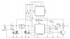
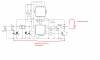
Here is what I'm going to build.Is that ok?

In my project it has a relay & from the relay it will control 230V AC, so this power supply must smooth any spike coming from the surrounding world.
 

Attachments

  • 5V Supply.JPG
    5V Supply.JPG
    18.5 KB · Views: 592
Did you intend C3 to be 100nF ceramic (not 100uF electrolytic)?
12-0-12 is rather high, causing unnecessary power wastage in the 7805. Could you use 9-0-9?
Don't forget a back-emf suppression diode across the relay coil.
 
Hi thanks for pointing out.

I will replace 100uF & place a 0.1uF.

I have 0.1uF MLCC capacitors.As those are expensive I'm going to use on the output side of the regulator.

0.1uF disk capacitors I'll use input side of the regulator.
 
Even with all those capacitors in the power supply, your micro is still going to be vulnerable to ground loop disturbance if you dont keep the relay coil ground return current away from the micro's ground.

Also, I would get a relay that I could operate directly off the unregulated input to the 5V regulator; no point to running the relay coil current through the regulator. The relay coil current shouldn't flow along the micro's supply line.

C3 needs to be close to the micro; not close to the voltage reg.
 
Last edited:
Seems high. Do you have a good ground on the scope?

What is the load the relay switches. You may want a snubber.

And like Alec said don't forget the diode across the relay coil.
 
Post your circuit schematic.

What is the min/max unregulated voltage going into the regulator?
 
Here is the circuit.It has a continuous ripple of 200mV on Power lines.

When the circuit is in standby mode the LED is blinking.

Does the 7805 not have enough load to regulate?
 

Attachments

  • 5V ripple sch.JPG
    5V ripple sch.JPG
    53.3 KB · Views: 407
What is the voltage on C1? How much ripple is on that voltage?
Is the LED intended to blink in standby mode?
Can you increase the 7805 load temporarily to see if that changes the ripple?
 
Oops sorry I have not mentioned the transformer voltage.Its a 12-0-12 transformer.

C1 is 25V.

When the switch pressed the LED starts to blink @ half a second rate.The timer starts to count up.The relay will be off.When the timer reaches 12 hours the relay will be ON.
 
Guys I checked with the oscilloscope.

The regulator output shows a 200mV ripple.Is this normal?

I would suggest the ripple is due to a measuring error - it's sometimes difficult to get proper reading with a scope.

The capacitors aren't there to filter noise as such, the 1000uF is the reservoir capacitor, and the two 100nF are to prevent the 7805 oscillating - the 100uF on the output probably isn't needed.

As for the LED flashing, presumably the program is supposed to do that?.
 
Here is the circuit.It has a continuous ripple of 200mV on Power lines.

As Nigel stated this is probably measurement error. To check you can leave your scope ground on ground where you have it now and probe the same ground lead an inch away. It should obviously be zero since it is just a wire so any reading is measurement error. You can also measure the frequency of the noise. If it is ripple in the classic sense it will be at 100 Hz. If it is at some other frequency (say 50 Hz.) it is probably noise pickup on your scope leads.


Does the 7805 not have enough load to regulate?

The 7805 has a built in minimum load.

I added a couple of things to your schematic as a precaution not related to the ripple. One is to have the relay current go straight back to the power supply and not thru any of the logic ground.
Two would be where the snubber would go if the relay load is a motor or something else inductive.
 

Attachments

  • pic.png
    pic.png
    69.2 KB · Views: 328
C1 is 25V.
I didn't mean the voltage rating. What voltage do you measure between the terminals of C1 and how much ripple is there on that voltage?
 
Hi thanks for the points.My load is a motor.

Here is my PCB design.

The yellow colour line is the ground return path of the relay.

1st is the old PCB
2nd is the edited.

Any improvements?
 
Last edited:
Suraj,
place 0.1uF disc or MLC capacitors across each diode. Take the observations then.
 
Hi thanks for that point.

The first two diodes are rectifying diodes.The three pin connector is the center tap transformer output.The other diode is the free wheel diode across the relay coil.

I'll place 0.1uF ceramic disks on each diodes.

May I know whats the reason to use such a thing?
 
Looks better. Since the load is a motor you will probably need a snubber on the relay or it will arc when it opens and the noise from the arc may upset your micro. Snubbers are tricky. Have a Google and tell us the specs on your motor.
 
Status
Not open for further replies.

Latest threads

Back
Top