Continue to Site

Welcome to our site!

Electro Tech is an online community (with over 170,000 members) who enjoy talking about and building electronic circuits, projects and gadgets. To participate you need to register. Registration is free. Click here to register now.

  • Welcome to our site! Electro Tech is an online community (with over 170,000 members) who enjoy talking about and building electronic circuits, projects and gadgets. To participate you need to register. Registration is free. Click here to register now.

555 toggle help

Status
Not open for further replies.

the judge

New Member
i want to turn a couple of garage door openers into general switches for prototyping and other things, but the relay on the receiver only activates for about 2 seconds when it gets a signal and i want it to turn that into just a toggle
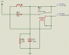
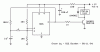
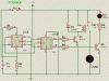
i tried this circuit and when i pressed the switch, it turned on, but when i pressed it again it didn't turn off. could pins 5 and 7 floating be the problem? i'v tried replacing the capacitor, transistor, and 555 chip, even though they all worked when i tested them. at this point i'm checking to see if there are wizards around making the electricity not work (yes i'm that frustrated)
 

Attachments

  • 555-T.gif
    555-T.gif
    2.7 KB · Views: 447
Hi,

here's a circuit for a good toggle switch. /Q is high when the circuit is energized indicating "READY". When the pushbutton is pressed /Q goes low and Q goes high activating the relay.

Pressing the pushbutton again the circuit returns to ready state.

Look at the attached screenshots. The relay is an animated one and switches the "LOAD" (light bulb)

Boncuk
 

Attachments

  • TOGGLE-1.gif
    TOGGLE-1.gif
    14.2 KB · Views: 1,149
  • TOGGLE-2.gif
    TOGGLE-2.gif
    14.2 KB · Views: 660
You can't toggle using an NE555. Toggle function can be achieved by connecting a JK-FlipFlop at it's output.

A CD4027 is 15 Cents.

Using a 4027 you might save the timer IC for other applications.
 
Last edited:
But you can toggle using two 555s or a 556 ;) **broken link removed**
Ken
 
for that schematic, what do i do with pins 1, 4, 10, and 13? also the output pins aren't even shown, do i just leave them floating?
 
for that schematic, what do i do with pins 1, 4, 10, and 13? also the output pins aren't even shown, do i just leave them floating?
Before we answer that, give us more info on the signal that you want to use to initiate the toggle:
1. Are you using the relay contacts, or the signal that drives the relay?
2. What are the high/low voltage levels?
3. Are rise and fall times reasonably fast (a few microseconds or less)?
4. What power supply voltage(s) do you have available?
5. What kind of load do you want to drive?
 
the input that im trying to turn into a toggle is relay contacts. when i connected the + to one of the outputs and the - to gnd, i got about 5.4v for high and about 3mv for low when the supply voltage was about 7.2v. when i tested it with the pins 1, 3, 4, 10, 11, and 13 floating and leds between the outputs and gnd, the leds turned on randomly (they stayed on not blinking but each time i turn it on, it gives me a random result) and for the switch i just got a wire and touched it to one of the contacts so i don't know the rise and fall times, but i would think it would be fast. the supply voltages i have are anywhere from 1.2v to 32v, but i think the max voltage for the chip is 16v. the load i want to drive right now is the discharge of a 330v 30milifarad capacitor bank for a coil gun (which is why i don't want to be too close to it when i test it), but i want to use it for other things. mostly prototyping.
 
Touching two wires is about the worst thing you can do triggering a timer (and any other digital) circuit.

Guess how many bounces you create when touching the two wires. :)

The worst quality pushbutton won't get that rate.

I also recommend to make some "dry runs" before you apply high voltage.

Boncuk
 
You should be able to do it like this.

EDIT: This may not work, due to bounce when the contacts open.
See post #17 for a possible fix.
 

Attachments

  • toggle ff with input debouncer.PNG
    toggle ff with input debouncer.PNG
    25.8 KB · Views: 492
Last edited:
IT WORKS!!!!
i tried the 4013 circuit and used relays instead of just touching wires and it worked! also i had no idea that touching wires had a lot of debouncing, thanks for the tip and thank you everyone for your help, but i do have one more question, in that diagram, is pin 2 floating? i heard that if a 4013 has a floating pin it gets damaged
 
Floating inputs will cause the device to malfunction. Floating outputs are fine.
 
Last edited:
If you put the R1 and C1 time constant on the toggle FF between Q/ and D, you don't need a separate debounce FF.
 
If you put the R1 and C1 time constant on the toggle FF between Q/ and D, you don't need a separate debounce FF.
That seems like a good idea, but won't the FF also toggle when the switch is released?
 
oops. You're correct. It would toggle any time the switch bounces, which would include release.

[edit] Actually both designs would work this way. Probably not a problem with a N.O. contact where it's shown. [/edit]
 
Last edited:
oops. You're correct. It would toggle any time the switch bounces, which would include release.

[edit] Actually both designs would work this way. Probably not a problem with a N.O. contact where it's shown. [/edit]
Oops. I think it is a problem. It showed up in the simulation, but I missed it. Below is a somewhat clunky way to fix it, at least in simulation.
If you use a 4013 with a Schmitt trigger clock input, you don't need the first FF. A simple RC network will debounce the switch. Unfortunately, the only one I know of is HEF4013 from NXP (Philips). There may be others.
 

Attachments

  • toggle ff with input debouncer1.PNG
    toggle ff with input debouncer1.PNG
    24.5 KB · Views: 214
Here's a clever circuit to toggle a relay:

**broken link removed**
Short tone = ON Long tone = OFF
 
Last edited:
Another clever relay toggle circuit.

Ken
 

Attachments

  • PushOnPushOffRelay.gif
    PushOnPushOffRelay.gif
    6.9 KB · Views: 198
Since I suppose the OP doesn't want to use a 24V power supply I simulated the circuit applying 12V.

At a coil resistance of 300Ω the minimum value for R1 should not be less than 39Ω. If it is smaller the relay will toggle on when the button is depressed, and toggle off for a short moment and on if the button is depressed again.

With R2=330Ω the minimum time between button operations should be approximately 500ms (for the electrolytic cap to discharge below 9V)

The value of R2 should not be lower than 240Ω. (Otherwise the relay won't switch on.)

Boncuk
 

Attachments

  • REL-TOGGLE-01.gif
    REL-TOGGLE-01.gif
    7.2 KB · Views: 207
  • REL-TOGGLE-02.gif
    REL-TOGGLE-02.gif
    7.2 KB · Views: 200
Status
Not open for further replies.

Latest threads

New Articles From Microcontroller Tips

Back
Top