Continue to Site

Welcome to our site!

Electro Tech is an online community (with over 170,000 members) who enjoy talking about and building electronic circuits, projects and gadgets. To participate you need to register. Registration is free. Click here to register now.

  • Welcome to our site! Electro Tech is an online community (with over 170,000 members) who enjoy talking about and building electronic circuits, projects and gadgets. To participate you need to register. Registration is free. Click here to register now.

555 timer

Status
Not open for further replies.

rickyrick0465

New Member
want to use a 555 timer to switch a PNP transistor on for 20 seconds.
I do not know how to wire it
Can someone point me in the direction of a circuit, please
Thanks
Rick
 
Missing way too many details:

Operating voltage for the 555.
Voltage the PNP transistor is switching (it could be different).
Peak current the PNP transistor is switching.

What is the load the PNP transistor is switching? Importantly, is one end of the load connected to the same ground as the 555 circuit?

These details matter because a PNP transistor usually is used to switch a load up to a positive DC voltage, as opposed to an NPN transistor pulling a load down to GND. The problem is that a bipolar 555 output stage cannot swing up close enough to VCC to turn *off* the transistor after the timing period. There are several different ways around this.

Are you going to use a bipolar or CMOS 555?

ak
 
Im switching 2 amp motor at 12v. Was going to use FQP30N06L
555 time is NE555P
Yes was planning to connect all grounds
Thanks Rick
 
How accurate do you want your 20 sec turn on time ?

The trigger to turn on, simple switch or analog or logical qualified trigger ?

Do you care about power up transients ?

Regards, Dana.
 
20 seconds give or take it does not matter
I want the circuit to turn on a bilge pump.
with the float switch, im using the disturbance in the water makes the switching cycle on and off. I want the 555 timer to prevent that just by keeping the pump on for 15 or 20 seconds
Rick
 
want to use a 555 timer to switch a PNP transistor on for 20 seconds.
I do not know how to wire it
Can someone point me in the direction of a circuit, please
Thanks
Rick
You mention using a FQP30N06L which is a N channel MOSFET (Logic Level) but you mention a PNP transistor? Not sure about that? Anyway using a FQP30N06L MOSFET you would configure the 555 timer as a "one shot" so you get a 20 second (approximately) pulse out when triggered. This can be a retriggerable or non retriggerable one shot. You have water sloshing around in the bilge. The difference between retriggerable and non retriggerable is when the bilge switch turns on the retriggerable one shot will maintain a logic high (pump running) as long as the bilge switch is ON/Off from sloshing. Once the switch is Off and remains Off the pump will run for an additional 20 seconds. Non retriggerable once triggered the pump will run for 20 seconds regardless of what the switch is doing. Once it times out it waits for another trigger.

The FQP30N06L would be used for low side switching of the pump. Meaning it would switch the negative pump lead. The pump positive would always be connected to battery +.

Ron
 
Ok so if I wanted to switch the positive side of the pump I would use a p channel Moffett?
This goes back to my original question how do I wire the 555 timer.
Right now I'm using a capacitor and a very small relay that controls a larger one
Thanks Rick
 
Almost there.

Is there a trigger signal, or do you want the pump to run whenever power is applied to the circuit?

ak
 
There is a float switch that would start the 555 timer
So float switch would turn on and maybe Bob up and down a few times (on and off) with the rippling water, the timer would either time out 20 sec from the last float switch on or from the first on. It does not matter
 
Last edited:
The circuit and the design equation are on this page:

1647201446462.png


Pin 3 connects to the output device. If you change to a CMOS 555 (LMC555, etc.), it will drive a FET correctly with no additional parts. If you go with a bipolar 555, an additional resistor and small zener diode are needed to guarantee turn-off.

ak
 
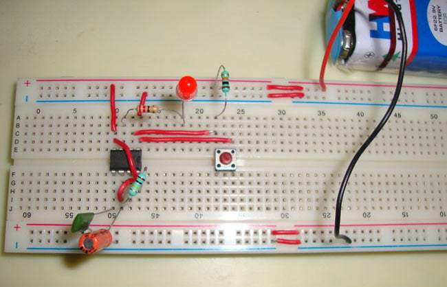
I wired up the circuit above and on pin 3 of the 555 timer I get power only when the pushbutton is depressed. let go of the switch and no voltage on pin 3
Checked wiring and its correct.
I'm under the assumption that when using the p channel (FQP27P06) that I have to apply neg voltage to the gate for the circuit to turn on (switching the positive side)
Even if the timer was to stay on. Pin 3 is positive
 
I wired up the circuit above and on pin 3 of the 555 timer I get power only when the pushbutton is depressed. let go of the switch and no voltage on pin 3
What values did you use for R1 and C1.
Sounds like they may be too small.
 
I wired up the circuit above and on pin 3 of the 555 timer I get power only when the pushbutton is depressed. let go of the switch and no voltage on pin 3
Checked wiring and its correct.
I'm under the assumption that when using the p channel (FQP27P06) that I have to apply neg voltage to the gate for the circuit to turn on (switching the positive side)
Even if the timer was to stay on. Pin 3 is positive

Use an NPN or NMOS transistor to switch the PMOS transistor on/off.
Like this:

1648881992077.png


Might also need a 1N4007 diode from pump+ to ground.
 
Last edited:
Status
Not open for further replies.

Latest threads

New Articles From Microcontroller Tips

Back
Top