Continue to Site

Welcome to our site!

Electro Tech is an online community (with over 170,000 members) who enjoy talking about and building electronic circuits, projects and gadgets. To participate you need to register. Registration is free. Click here to register now.

  • Welcome to our site! Electro Tech is an online community (with over 170,000 members) who enjoy talking about and building electronic circuits, projects and gadgets. To participate you need to register. Registration is free. Click here to register now.

555 timer question

Status
Not open for further replies.

apl247

New Member
My project involves counting how many times an accelerometer sensor outputs a voltage above a certain threshold in time parameters of one minute and one hour.

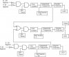
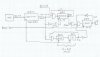
I am using a 555 timer circuit ANDed with the sensor output, which then feeds into a digital counter. Am I correct to use the 555 timer in monostable function?

I am wondering about the triggering. I want the timer to start when the power is connected. During the minute when the timer is outputting high voltage, the counter will count up how many times output from the AND gate is 1. But when the minute is up, I want the timer to restart and have the counter reset as well. But at the same time, say if the counter reaches 30, it will stop the timer whenever it may be, and restart it.

So I need have an auto trigger on the 555 timer to restart itself after each minute but also a trigger that allows the output from the counter to interrupt and restart the timer.

Any ideas?

Thank you!
 
What do you do with the two counts? How are they displayed? How long do the counts have to be valid?
 
There is only one count. The timer ANDed with the sensor output is to make the sensor output valid only when the timer is going.

The counts are not being displayed, the output from the counter goes to a magnitude comparator that is set to 30. So when the count is over 30, it will output high and when under 30, will remain low.

The counts are valid for as long as the timer is going (my time parameter of 1 minute).

I have attached a block diagram that may be more helpful in explaining what I am trying to do..
 

Attachments

  • digital block schematic2.jpg
    digital block schematic2.jpg
    31.5 KB · Views: 190
Ok, why are there three different 555's? Or is there just one that gates all three count channels?

Why are you separately counting the two accelerometer axes?
 
It should be just one 1 minute timer that is gated to the count channels.

There are 2 different voltage thresholds from the two axes of the accelerometer, and the system must detect both voltages before outputting "high", corresponding to a successful detection/a valid count.
 
It should be just one 1 minute timer that is gated to the count channels.

There are 2 different voltage thresholds from the two axes of the accelerometer, and the system must detect both voltages before outputting "high", corresponding to a successful detection/a valid count.

Then why not detect the two channels separately with their own respective thresholds and then AND them together with the 555 Gate (three input AND gate) and then have only one counter?

ps-I know I'm not answering the question you asked, but trust me, this is going somewhere :D
 
I need multiple counters because one counter (top one) is counting how many times the accelerometer is sensing a tilt of +20 degrees and the 2nd counter is counting how many times a -20 degrees tilt is detected. But I can use just one 555 timer to have the 1 minute time parameter right?

Thanks for your help by the way!
 
Ok, but based on your diagram, you produce an alarm if the total number of pertubations of the accelerometer exceed 5x30, regardless of which channel was detected. So I should have proposed CountUp=(Det1 OR Det2) AND 555.

Answer this while I am writing about how to control the 555.
 
how accurate do you want the time?

my first thought was 3- 4017's chained together = 30
have the clock pulse ANDed to the clock input.
when 30 is reached then pin 13 on the last 4017 is connected to an AND gate which resets the 4017's.
a 556 has 2-555's in it. set one up with a xtal for 1hz pulse and then a divide by 60 circuit for 1 hour
another method would be a 4518 utilizing the counters together, then using gates decode the outputs for a 30 count.
just some food for thought.
 
Yes, I want to a produce an alarm when the counter detects 5X30 regardless of which channel. But for this, time parameter is an hour. I would need a separate 555 timer for this. But I think your proposed CountUp works.

But with the individual channels (top and bottom part of the diagram) I want to produce an output (lit LED) when the count is over 30 within the time parameter of 1 minute, so don't I will need separate counters for that CountUp function? I could use one 555 timer, set to 1 minute, to gate these two detection channels.
 
Ok, I was just looking at your diagram and I have another question. What happens when either counter reaches 30? Does it reset to zero, or does it count to 31 before resetting naturally because it is a 5 bit counter?

If so, why bother with the magnitude compare? If you dont reset it, then it will take 32 more counts before the magCompare is asserted the second and subsequent times.
 
I need to reset the counter when it reaches 30. I want the counter to reach 30, pass on the signal to output the LED, stop there, and reset to 0.
 
Yes, I want to a produce an alarm when the counter detects 5X30 regardless of which channel. But for this, time parameter is an hour. I would need a separate 555 timer for this. But I think your proposed CountUp works.

But with the individual channels (top and bottom part of the diagram) I want to produce an output (lit LED) when the count is over 30 within the time parameter of 1 minute, so don't I will need separate counters for that CountUp function? I could use one 555 timer, set to 1 minute, to gate these two detection channels.

Two things: if you want two separate LEDs and all four states that they imply, then you will need two separate counting channels. The other thing is that counter=30 is a transient state, so you should latch the mag compare output the first time it happens so that the LED means "at least 30 events occured since we started"
 
I need to reset the counter when it reaches 30. I want the counter to reach 30, pass on the signal to output the LED, stop there, and reset to 0.

Ok, then ditch the magnitude compare and use the Thumbwheel switches to preset the counter to (32-TWS); this creates a modulo TWS counter. Or, use a down-counter and just preload the TWS value directly.


Then the carry-0ut (roll-over from 31 to 0) of the counter can be used to increment the final counter.
 
Last edited:
I didn't know about thumbwheel switches, was just reading about those now. Thanks for the suggestion.

Would using that make it easier to control the resetting of the timers?
 
I didn't know about thumbwheel switches, was just reading about those now. Thanks for the suggestion.

Would using that make it easier to control the resetting of the timers?

Ok, let's get to that. Look up "variable modulus counters" or "programmable dividers". Is the value in the TWS anything from 2 to 31, set by the user, or is it just a fixed number=30. If it is always 30, then you do not need the TW-Switches, you just need to build a counter with a modulus of 30.

What is the use model for this thing? Is there a single RESET button which starts the entire process? If so, it could be used to reset all the counters and to start the timing interval(s).

I am still confused about meaning of the ALARM. Is the alarm supposed to come ON only if 30*5=150 pertubations of either accelerometer channel have occurred during the one hour after the system was last RESET?

If this is true, then what is the one minute period used for? It seems to me that the one minute period has nothing to do with the one-hour ALARM function. This would imply separate; not cascaded counting chains.

You may have separate requirements that says "light an LED if ≥30 events have occurred since the RESET was pushed" or "light an LED if ≥30 events have occurred in the last minute". The former of these is easy, the latter is much harder.
 
The Alarm:
Yes, it is supposed to come ON if 30*5 pertubations have occurred during the one hour after the system was last reset.

Yes, the one hour alarm and one minute timer are separate, but are occurring at the same time. The reason why the one minute period is important is because the 30 pertubations must occur in a one minute period. However, I want the alarm system to be activated when those 30 pertubations in one minute have occurred 5 times in one hour. In other words, the system starts and both one hour and one minute timers would start, with the one minute timer being the time base for the counter and when COUNT>30, pass signal to light LED and also to increment the hour time period based counter.

As I mentioned before, I want the one minute timers to continuously be reset after each minute. So the counter can restart the count. The parameter is that 30 pertubations must occur in one minute. I"m not sure if that answers your last question. Since, I want to light an LED if >30 events have occurred since the RESET (but that also makes the second statement true because I want each reset to be a one minute interval).
 
btw- mrDEB had a good suggestion. When you need to accurately time intervals, the 555's repeatability is not better than about 2-3%, depending on temperature, and especially as the timing interval gets longer.

If you really need to time an hour accurately, then use a 4020 14 bit up counter. After a reset, it takes 2^13=8192 counts for Q14 to go high, so run the 555 as an astable at a rate of 1/(3600/8192)=2.26Hz. Or use a 4541 which is a 16 bit counter with a latching output which goes low (and stays low) after 2^16=65536 counts. For this your astable 555 would run at 1/(3600/65536)=18.2Hz.

The 4541 chip (plus the 555 or other astable) would produce the entire timing chain for the one hour period. It would stop after the hour, with the ALARM on or not, holding that state until the RESET was pushed to begin the cycle over again.
 
The Alarm:
Yes, it is supposed to come ON if 30*5 pertubations have occurred during the one hour after the system was last reset.

Yes, the one hour alarm and one minute timer are separate, but are occurring at the same time. The reason why the one minute period is important is because the 30 pertubations must occur in a one minute period. However, I want the alarm system to be activated when those 30 pertubations in one minute have occurred 5 times in one hour. In other words, the system starts and both one hour and one minute timers would start, with the one minute timer being the time base for the counter and when COUNT>30, pass signal to light LED and also to increment the hour time period based counter.

Ok, try this. Suppose you build a 555 always-running non-gated oscillator (astable) which runs at 136.53 Hz (period is 0.00732sec). You use that to clock a 13 bit binary up-counter, such that on the 8192nd clock, the counter resets for one clock period, and then starts counting again. This produces a gating signal (GATE) which is high for 60sec, and is low for 7msec. I help you do this.

You use this to gate the accelerometer events into their respective counters (Event Counters). They count while the GATE is high; they reset when GATE goes low. The Event Counter is a special counter that counts 0 to 31, but stays at 31 (i.e. it doesn't overflow back to zero) if it gets more than 31 counts during GATE.

There is a decoder on the Event Counter that is true if the value is either 30 or 31. On the high to low transition of GATE, if the decode is true, you increment the Alarm Counter. It takes a four input AND gate to do this decode.

You need another counting chain which creates the one-hour interval. Use the trailing edge of GATE to increment a counter capable of counting to sixty. This could be implemented as a decade counter followed by an octal counter, where you decode "six" in the octal counter. In other words, the one hour interval ends when the count rolls from 59 to 60. It takes a 4 input AND gate to do this. Call the output of this decoder HOUR.

The Alarm counter is a three bit counter as you drew it, except that is has to count up to 5 and then hold at 5 even if more pulses come in. It will take a decode of this counter to detect state 5 so you can arrest it from counting higher. You also use this same decode to sound the alarm horn.

The RESET button resets all of the counters to initialize everything for a new cycle.

btw- this is entirely too much damn work. I would have put all of this logic inside a PIC in the same time as we have been discussing it...:D
 

Attachments

  • Accel.jpg
    Accel.jpg
    208.2 KB · Views: 172
Last edited:
Status
Not open for further replies.

Latest threads

New Articles From Microcontroller Tips

Back
Top