pcbheaven: your using a pullup resistor on pin 7 to create the output signal to drive the mosfet, this is a good way of doing it however it has nothing to do with the actual operation of the circuit, the actual circuit drive is the same as what i have you are using pin 7 coupled with a resistor to drive the mosfet I am not driving anything at all just sampling pin 3 with a scope, if I were to drive a mosfet weather or not I use pin 3 or 7 (with the extra resister) it would make no difference to the circuit actually working.
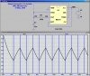
Eric: yes its a dual channel scope, I think my simulator is playing me up

")