Continue to Site

Welcome to our site!

Electro Tech is an online community (with over 170,000 members) who enjoy talking about and building electronic circuits, projects and gadgets. To participate you need to register. Registration is free. Click here to register now.

  • Welcome to our site! Electro Tech is an online community (with over 170,000 members) who enjoy talking about and building electronic circuits, projects and gadgets. To participate you need to register. Registration is free. Click here to register now.

555 timer keeps blowing up.

Status
Not open for further replies.

Screech

New Member
555 timer keeps blowing up

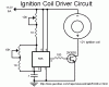
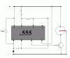
I built an ingition coil driver useing the below schematic, but I wired the coil the other way round.
I made sure that positive voltage went to the positive of the coil.
Is the schematic wrong?
It even works using a small 9volt battery.


The timers that I have been using are ne555.
Is there a way to protect the timer?
 

Attachments

  • coildrv.gif
    coildrv.gif
    5.8 KB · Views: 3,028
Put a diode across the emitter and collector of your transistor in the direction opposite to the current flow through the coil. When the current pulses through the coil the diode won't affect it. When the current stops flowing, the magnetic field around the coil collapses. This creates a large voltage in the opposite direction (which is what is probably destroying the 555). The diode will bypass this to ground, protecting the 555.
 
Also the 1k resistor is less. It should be above 5k so that min. value of R remains 5k even when pot. is set to zero ohms.
The 2N3055 driven using 555 seems an overkill for this IC. Use 555's output to drive medium power transistor and use this transistor to drive 2N3055.
 
E = -L(dI/dt)

Both posts make good points, but lavenatti's right, it's the lack of a protection diode that's blowing your parts. It's a common mistake. Are you finding that your 2N3055s are blowing up as well?

When the current through a coil changes with time, an electromotive force is induced in the coil. Faraday's law says that an instantaneous change in current will produce an infinite voltage. Instead of that happening, the silicon junctions in the coils' path break down and provide a path to ground. You can bypass the coil with a diode, zener, or a snubber (RC); power supply rectifiers like the 1N400x are often used. You'll often see the diode wired across the coil in a reverse-biased manner, this basically provides a short circuit for the transient (notice the minus sign in the equation...).
 
A shotkey diode across the Collector and emmitter will solve it...maybe. But to totally get rid of the voltage spikes that are killing your 555, get a 12v transient suppressor diode. kinda like a zener but way better
 
You might also want to consider putting the 555 on a separate power supply with a common ground connection .
 
:lol: Thanks guys. I will do what you say.

since I only had an MJ10012 (10 amp Darlinton) transistor around, I used it instead of the 2N3055.
by the way, the transistor is not dieing.


I've bought some schotty diodes(1N5819) the other day. I'll try them.
If they don't work, I'll try using two seperate power supplies.

Oh, I'll look into those 12v transient suppressor diodes and the zeners.

Thanks for the Help.
 
dead 555s

The power darlington wouldn't necessarily get damaged. The coils' transient spike finds the easiest path to ground, and the 555s' output stage is probably "popping" or fusing before any damage occurs to the power transistor. The 555 makes a good "electronic fuse" in this circuit. At least that's my guess.

You often see peripheral driver ICs with built-in protection diodes (ex: ULN2003A).
 
Yeah, and notice that the diodes are designed to be placed across an inductive load, NOT from collector to emitter. If the freewheeling diode is in place and not defective, there should never be a negative spike at the collector of an NPN common-emitter stage driving an inductive load, so a diode from collector to emitter serves no purpose.
 
One more thing, put the diode across the coil terminals if possible, to minimize the current loop when the transient occurs. ie, if the coil is located an appreciable distance away from the driver circuit, put the diode across the coil, as opposed to back on the board where the driver is located.
 
Yeah, and notice that the diodes are designed to be placed across an inductive load, NOT from collector to emitter

But this defeats the purpose of the coil. The whole point of the coil is to get a large reverse voltage, which creates a spark at the spark plug. If you suppress this voltage with a flywheel diode, then you get no spark. :(
 
But this defeats the purpose of the coil. The whole point of the coil is to get a large reverse voltage, which creates a spark at the spark plug. If you suppress this voltage with a flywheel diode, then you get no spark.

Exactly Phaser, so like i said earlier put the 555 on its own separate power supply connected via a common ground to the power transistor , problem solved.
 
catch-22

phasor is right, the diode will protect your 555 but kill the spark. Overlooked the obvious :oops: . For most other coil driver scenarios, (relays, solenoids, motors) the protection diode would be a good fix, and the previous advice applies. Nettron has a good solution here.
 
Hi Screech,
I think lavenanetti's idea of a diode across the 3055 is a good idea and may prevent the back-emf from entering the 555 through the transistor.
One more thing that may help is putting a diode either in series with the + side of the coil or as a shunt (cathode to +) from the supply to ground. This will also prevent back-emf from entering the 555 through the power rail.

Good luck on your project, let us know how it works.
 
When i get around to buying some more 555 timers I'l let you all know how I go.

I havent heard anyone mention capacitors.
I recently read an article that robot makers use lots of caps near ic's to absorb similar spikes when running dc motors, and diodes near the motors. And they like using seperate power supplies.

What do you guys think about using caps for absorbing spikes?
and thanks for all the input. :p
 
How do you place the 555 on a seperate power supply

I am too building the above circuit and keep blowing 555's.
It is looking like the answer is to suply the 555 with it's own power.

Can some one draw a schematic up so the 555 is on a 9v battery and the coil is driven on 12v.

The transistor seems to get VERY hot, is this caused from feed back from the coil?

If so what can be done to help it out.

Kev.
 
The current through the coil builds up with a time constant tau=L/R, where L is the primary inductance and R is the series resistance in the coil/transistor circuit. If you turn the transistor on long enough to reach I=V/R (about 5*tau), the current will be limited only by the series resistance in the circuit. If that is only the primary resistance of the coil, your transistor may indeed get hot. You may need to either use a series resistor, a shorter ON time, a heat sink, higher base drive, or a bigger transistor.
 
add a diode and a 470 uf cap.
The circuit works excellent now.
pic attached:
 

Attachments

  • sparky.gif
    sparky.gif
    7.4 KB · Views: 954
Not sure about the frequency.
Cant remember the resitor values, but under 10 k.
The circuit does not have to have a precise frequency for a big sparks.
The spark size is also dependent on the supply voltage.
I'm getting over 2 inch sparks on 12 volts.
very impressive.
 
Status
Not open for further replies.

Latest threads

New Articles From Microcontroller Tips

Back
Top