Continue to Site

Welcome to our site!

Electro Tech is an online community (with over 170,000 members) who enjoy talking about and building electronic circuits, projects and gadgets. To participate you need to register. Registration is free. Click here to register now.

  • Welcome to our site! Electro Tech is an online community (with over 170,000 members) who enjoy talking about and building electronic circuits, projects and gadgets. To participate you need to register. Registration is free. Click here to register now.

555 timer DELAY - please review and advise

Status
Not open for further replies.

nickm304

New Member
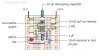
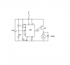
Ok, So I read a couple threads here about setting up a delay with the use of the 555 timer and I have constructed a circuit identical to the one "attached"

Basically, I am looking to hook up a small dc motor and have 45-60 seconds go by before the motor starts.

I am using a 47 mF capacitor and a 1M ohm resistor, So I believe this should provide just over 50 seconds of delay.

So I switch out the 1 mF capacitor (in the diagram) with my 47mF, and I use the same 1M ohm resistor. my question(s)..

1.) Do I need to change the values of the 10 k "pull up resistor" ?
2.) how about the 10 mF decoupling capacitor?
3.) I assume I swap out the LED with the dc motor,..correct?
4.) the 680 ohm resistor in front of the led,...do I need to change that value?
5.) lastly, what is with the 10 nF element, that says optional?

thanks a million, I really appreciate the help!
 

Attachments

  • untitled.JPG
    untitled.JPG
    32.1 KB · Views: 485
The timer does the opposite to what you want. It starts lighting the LED (or driving the motor) immediately when the button is pressed and it stays on for about 45-60 seconds.

The 10k pullup rersistor must connect between pin 2 and the positive supply. The pushbutton is supposed to connect pin 2 to 0V when it is pressed.

The 10uF decoupling capacitor is needed.

Swap the LED and resistor for the motor. Use the resistor only with an LED.

The 10nF capacitor is needed if the supply voltage varies all over the place.
 
thanks for the quick response,..hmm well that is unfortunate that it doesn't do what I want. So what would the circuit be called that I am looking for? Is there an easy circuit I could build to accomplish this task?
thanks
 
You can't just reverse the motor (or LED) connection to +9V instead of to 0V. Then the motor will start when the power is turned on, turn off for 45-60 seconds when the pushbutton is pressed then start running again.
I think you need two timers. The first one triggers the second one.
 
thanks for the quick response,..hmm well that is unfortunate that it doesn't do what I want. So what would the circuit be called that I am looking for? Is there an easy circuit I could build to accomplish this task?
thanks
A couple of questions: What is the voltage rating of the motor and how much current does it draw on that voltage.

I can think of two solutions: If you replace the push button switch with a 0.1uF capacitor the 555 will start the timing when the power is applied. If you connect a relay coil to the output of the 555 with the NC contacts to control the motor the contacts will open as soon as the 555 starts timing and the contacts will close at the end of the timing cycle and turn on the motor.
Or you could connect a PNP transistor with the emitter to the + rail, the collector to one side of the motor. The other side of the motor to ground and a resistor from the base ot the PNP transistor to pin 3 of the 555. Put a 1N4001 diode in parallel with the relay coil and the motor. In both cases use a seperate switch to turn the power on to the timer and the motor circuit at the same time.
The relay or the PNP will turn the motor on at the end of the 45 second delay.

hmm I will try your second method tomorrow, I think I have most of those components, I do not have a relay coil on hand. I am kinda new to all this circuit stuff, I will have to draw out the diagram of what you are talking about and get back to you if I have any questions.

also, check out this link..

https://clarkson-uk.com/555-timer/operation/frames3.html[/B]

This circuit appears to be what I am looking for as far as I can tell, do you think this would work?
 
This circuit appears to be what I am looking for as far as I can tell, do you think this would work?[/QUOTE]

This is the schematic I recommend. When the power is first turned on the output of the 555 goes high and remain so for the timing period, then the output goes low and turns on the PNP transistor, which in turn energizes the motor.
The motor voltage and the motor current values are necessary to modifiy the circuit to work with the specific motor.
 

Attachments

  • 555 delay.png
    555 delay.png
    23 KB · Views: 387
The motor is just one of your generic 6-12v dc motors about 3/4 inch in diameter and 1 1/4 length. I do not have the motor right now to see what current it draws. I will try out a few things here and see what I can do.
 
This circuit appears to be what I am looking for as far as I can tell, do you think this would work?
This is the schematic I recommend. When the power is first turned on the output of the 555 goes high and remain so for the timing period, then the output goes low and turns on the PNP transistor, which in turn energizes the motor.
The motor voltage and the motor current values are necessary to modifiy the circuit to work with the specific motor.

ok I am about to try and make this circuit you showed in your last post,...I do not have a relay coil, I do not see it in the diagram either. Will I still need one, I know you mentioned something about using one a couple posts ago.
btw I really appreciate the help!
 
Last edited:
Status
Not open for further replies.

Latest threads

Back
Top