Continue to Site

Welcome to our site!

Electro Tech is an online community (with over 170,000 members) who enjoy talking about and building electronic circuits, projects and gadgets. To participate you need to register. Registration is free. Click here to register now.

  • Welcome to our site! Electro Tech is an online community (with over 170,000 members) who enjoy talking about and building electronic circuits, projects and gadgets. To participate you need to register. Registration is free. Click here to register now.

555 timer circuit grrr

Status
Not open for further replies.

jonnyjames1985

New Member
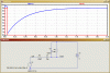
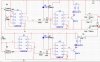
hi, im currently doing an electronics project, which i have designed with a bit of help. i am stuck trying to figure out one part of my circuit (see attached image), i have it working, but i dont know if the arrangement i have will function correctly when the circuit is made for real (it works in multisim). i have the first 555 timer (U3) set up to give high output until variable resistor r5 reaches 90%, then output low. this triggers the next 555 timer (U4). this gives me a timed output. as i said before it works on multisim but i cannot see how capacitor C2 can discharge. any advise would be much appreciated.
 

Attachments

  • circuit1.jpg
    circuit1.jpg
    66.2 KB · Views: 262
hi,
C2 will charge and discharge via R7 and the diode.
 
Last edited:
hi,
C2 will charge and discharge via R7 and the diode.

thats what i thought but the top of the diode is connected to positive, is the capacitor able to discharge this way or would i have to place the diode connected to negative? sorry i know im confusing myself with this
 
thats what i thought but the top of the diode is connected to positive, is the capacitor able to discharge this way or would i have to place the diode connected to negative? sorry i know im confusing myself with this

hi,
Its quicker to post a sim image than to explain it, look at this section from your circuit.
 

Attachments

  • AAesp03.gif
    AAesp03.gif
    21.5 KB · Views: 181
thanks for that, ive checked and im getting the same, but as part of the project im sure i'll be asked where and why it discharges?? also does the first part of the circuit look ok (u3), does triggering the 555 with resistors i.e no capacitors work in the real world. ive had no real experience with 555's before so dont know if this arrangement works
 
Question I have is what are you connecting the output transistor to?
You need a base resistor or the second 555 will emit magic smoke
 
Multisim is a good simulation software, but it should not be taken as the final word. First hand experience is the only experience that I use. I only use multisim to test whether or not 2 different circuits could be combined to make a bigger circuit and still function properly.

What I am wondering is what you are trying to do with these 555 timers. Could you post the full schematic of your circuit? We may be able to help you more if you give us more info.
 
magic smoke lol, yes a base resistor will be put in i just havent calculated what size yet, the output transistor is going to be used to control a relay which controls a motor for a certain time. i know ive over complicated the circuit a bit.
 
heres the full circuit so far. ignore the relay setup i cant find the correct ones to use on multisim. the circuit is designed as an automatic curtain closer, way over-complicated for what it is, and im using the 555's to time the motor, rather than using something like limit switches. any more advice?
 

Attachments

  • circuit1.jpg
    circuit1.jpg
    172.4 KB · Views: 210
Start over, that's my advice. I would suggest that you try using a comparator instead of a 555. A 555 timer is extremely hard to get timed perfectly, you would be best off making it a light activated circuit.

This actually sounds very similar to a kind of set up that I have in my house. All of the curtains and windows in my room are controlled by a semi complicated circuit and all of the heat/air vents are controlled by the same circuit. If it gets too hot, it will open a window unless it's hotter outside, then it will turn on a fan. If the AC or heat is on and one room is cooler/hotter than the others, it will open or close the heat vents to regulate the temp throughout the house. If it starts raining it automatically closes all of the windows. If it gets dark, it will close the shade, and if it gets lighter it will open them. There is not timing device involved, it just makes the changes when it sees fit to do so and I haven't had a problem with it yet.
 
Status
Not open for further replies.

Latest threads

New Articles From Microcontroller Tips

Back
Top