Continue to Site

Welcome to our site!

Electro Tech is an online community (with over 170,000 members) who enjoy talking about and building electronic circuits, projects and gadgets. To participate you need to register. Registration is free. Click here to register now.

  • Welcome to our site! Electro Tech is an online community (with over 170,000 members) who enjoy talking about and building electronic circuits, projects and gadgets. To participate you need to register. Registration is free. Click here to register now.

555 Low power Consumption Timer Circuit modification

Status
Not open for further replies.

hotter

New Member
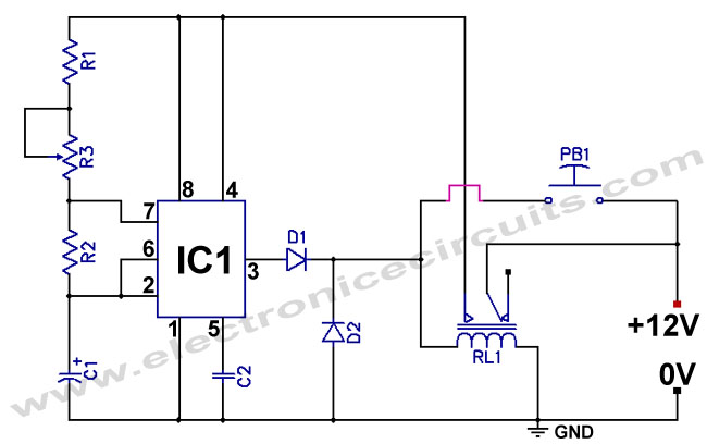
Hi, I would like to modifie this "555 Low power Consumption Timer Circuit":

555-Low-power-Consumption-Timer-Circuit.jpg


The problem is that I have push button already installed in a car and one side of it is connected to the ground.
Is it possible to adjust schematics to that button?

would this work and consume 0 power when off? Also wont Diods burn?
Any other ideas for such button placement and power consumption that would be 0 on idle?
 
Last edited:
Neither circuit uses any power, if PB1 is up (off). There cannot be any power flow since the relay contact (armature) is an open connection. Only when you press the button, does any power go to the 555 via the energized relay.
Where you put the PB1 does not make any real difference. In one, you are supplying the +12V to D1/D2 and the relay coil. In the second, D1/D2 get 12V all the time (but block it), and PB1 just completes the relay circuit by providing a ground.
Either way. PB1 is used to energize the relay, without which the 555 does not get power if not energized.

If the 555 holds the relay energized, your second diagram will not work, as pin 3/D1 cannot find a ground for the relay via PB1 if it is off.
 
would this work and consume 0 power when off? Also wont Diods burn?

It would not consume power when off - but the 555 does nothing, the relay coil is directly controlled by the button - it operates when pressed and releases when the button is released.

Rather than connecting the 555 output directly to the relay coil (which is now also +12V), you would need to add a transistor or FET controlled by the 555 output and connected across the button, so the 555 circuit maintains the power through the relay until it times out.

Or use the original and have you fitted button operate a relay and use the contacts of that where the button should have been.
 
Hi

In the top diagram, the 555 is configured as an astable. When the button, PB1, is pressed, the 555 will begin to oscillate at the frequency set by the RC combination. It will continue to oscillate as long as the button is held pressed. However, the 555 pulsed output to relay, RL1, is overridden by 12v from the button, so the relay will also stay energized as long as the button is held pressed. If the button is released before the end of the timing cycle, the relay will stay energized until the timing cycle completes

eT
 
And how could I edit shema that the button would be connected to ground?
Can pin 3 give negative ground instead of power? Or its not possible to modify shematicsthey way I want and that it wont consume power on idle?
 
And how could I edit shema
You don't need to.

Use a separate relay with one end of the coil to power and the other to your button to ground.

Then use the normally open contacts on that relay in place of the button in the original circuit.

That keeps the button as you have it, but within the circuit the switched (now relay contact) works to power.
 
And how could I edit shema that the button would be connected to ground?
Can pin 3 give negative ground instead of power? Or its not possible to modify shematicsthey way I want and that it wont consume power on idle?

What's the circuit suppost to do?
 
What's the circuit suppost to do?
I have the same question.
That's a strange circuit the way the relay and push-button are connected. (?)
 
What's the circuit suppost to do?
Circuit should do the same as original circuit in first post, except that it should have push button connected to ground instead of +12V.


You don't need to.

Use a separate relay with one end of the coil to power and the other to your button to ground.

Then use the normally open contacts on that relay in place of the button in the original circuit.

That keeps the button as you have it, but within the circuit the switched (now relay contact) works to power.
Nice idea!
This is my new circuit, is it correct?
555-Low-power-Consumption-Timer-Circuit.jpg
 
PB1 is just turning on a relay where PB1 was before. It is the same logic, just adding an extra relay between PB1 and original RL1. No need for second relay, it does nothing extra that PB1 can't do itself.
 
Circuit should do the same as original circuit in first post, except that it should have push button connected to ground instead of +12V

Yes...but what is it’s purpose? How is the circuit used?
There might be a simpler/ better solution..
 
And how could I edit shema that the button would be connected to ground?
Can pin 3 give negative ground instead of power? Or its not possible to modify shematicsthey way I want and that it wont consume power on idle?
Pin 3 can drive a transistor that can be in the negative side of the relay. The circuit below shows how to do it.
- You don't need the two diodes on the output of pin 3, but you do need the one I've shown across the relay.
- You haven't said what relay you're using. Some circuit changes may be necessary depending on what that is.

npn to gnd.svg.png
 
The diode across the relay coil can slow down the opening of the contacts. If a large load is being switched by the relay, opening the contacts slowly can cause contact burn.

The relay can be turned off faster if a zenner diode or resistor is put in series with the diode. A transistor of a higher voltage rating will be needed.
 
Pin 3 can drive a transistor that can be in the negative side of the relay. The circuit below shows how to do it.
- You don't need the two diodes on the output of pin 3, but you do need the one I've shown across the relay.
- You haven't said what relay you're using. Some circuit changes may be necessary depending on what that is.
But this will consume power on idle correct? Will my circuit with 2 realay work and wont consume power on idle?

Depends upon what it's supposed to do, which is not apparent. :confused:
Yes...but what is it’s purpose? How is the circuit used?
There might be a simpler/ better solution..
Circuit should not consume power on idle, and once turned ON it will do power LED and play sound with "Mono MP3 decoder module".
Original schematic is here: http://www.electronicecircuits.com/electronic-circuits/555-low-power-consumption-timer-circuit
For some reason in original schematic they do not point where LED is connected. I assume its pin3 and ground?
I just need that push button would be connected to the ground as its already installed and I would not like to change that.
555-Low-power-Consumption-Timer-Circuit.jpg
 
Last edited:
It's a pretty poor (and complicated) circuit, and will only play for a short space of time - FAR, FAR easier to use a little 8 pin PIC and a little programming, with a P-Channel FET to switch the power to the MP3 player. I presume the 12V supply is a mistake?, as providing 12V to the usual MP3 players would kill them.

So 8 pin PIC, a small push button, a P channel FET, and perhaps a resistor or two - and that's the lot, and you can program it to give as long a delay as you like, and far more accurate delays than a 555 will give. When it times out, simply switch the FET off, and put the PIC to sleep - consumption is as close to zero as you would ever need, and pressing the button wakes it up again.
 
The diode across the relay coil can slow down the opening of the contacts. If a large load is being switched by the relay, opening the contacts slowly can cause contact burn.

The relay can be turned off faster if a zenner diode or resistor is put in series with the diode. A transistor of a higher voltage rating will be needed.
True, but this is the industry accepted practice for probably 95% of applications, and will be the same as that of the original circuit that has a diode across the relay coil.
 
But this will consume power on idle correct? Will my circuit with 2 realay work and wont consume power on idle?
Both will work, and neither will consume power when idle. My transistor circuit would be a little smaller.

For some reason in original schematic they do not point where LED is connected. I assume its pin3 and ground?
Yes. But note that the total output current of the 555 is only 200mA. That should be plenty for what you're doing but keep that in mind anyway. This needs to include the relay, LED and the MP3 player. You'll also need a current limiting resistor for the LED.

And, as Nigel mentioned, 12 Volts is likely too much voltage for your MP3 player, so you'll probably need a voltage regulator to drop the 12 Volts down to what it needs.

How much time do you need this to run? With the values you show in post #15 it will run for about 12 Seconds.
 
The simplest and safest way of switching an external device from the original circuit is to use a two-pole relay for RL1.

One pole [set of contacts] is wired as in the diagram; the contact of the other pole are totally separate from all supplies and can be used to wire in series with the power of whatever device you want to control.

That also means the switching capability is that of whatever relay you select - typically 5A or more for a small plug-in type relay.
eg.
https://www.ebay.com/p/12v-DC-Coil-Power-Relay-Ly2nj-DPDT-8-Pin-Hh62p-Jqx-13f-With-Socket-Base/26007397847
 
It's a pretty poor (and complicated) circuit, and will only play for a short space of time - FAR, FAR easier to use a little 8 pin PIC and a little programming, with a P-Channel FET to switch the power to the MP3 player. I presume the 12V supply is a mistake?, as providing 12V to the usual MP3 players would kill them.

So 8 pin PIC, a small push button, a P channel FET, and perhaps a resistor or two - and that's the lot, and you can program it to give as long a delay as you like, and far more accurate delays than a 555 will give. When it times out, simply switch the FET off, and put the PIC to sleep - consumption is as close to zero as you would ever need, and pressing the button wakes it up again.

Hi I stumbled across this thread when I was searching the net, and it sounds like maybe someone here can help me.
I would also like to build a circuit with none or very little standby consumption.

It should be used to empty a barrel of water when it have been raining enough.
So that when the water reaches a certain point (two probes and a transistor make) the pump should start for about a minute and then the whole circuit should turn off, first I was sketching on something like the one in the beginning of the thread but with transistors, FETs and 555 but I’m stuck, I’m not very good at electronics but I find it very interesting,
If you have an example with a PIC and simple sketch, or a solution with the usual simple components I would be most grateful for some tips and tricks

Excuse my poor English I hope I make myself understood..

Best regards.
 
Status
Not open for further replies.

Latest threads

New Articles From Microcontroller Tips

Back
Top