Continue to Site

Welcome to our site!

Electro Tech is an online community (with over 170,000 members) who enjoy talking about and building electronic circuits, projects and gadgets. To participate you need to register. Registration is free. Click here to register now.

  • Welcome to our site! Electro Tech is an online community (with over 170,000 members) who enjoy talking about and building electronic circuits, projects and gadgets. To participate you need to register. Registration is free. Click here to register now.

555 begginner problems and ltspice simulation

Status
Not open for further replies.

normad

Member
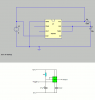
i looked up some articles and i think i understand the 555's monostable circuit.. but when i tried simulating it on ltspice i fail to get the expected results..

i have a few questions..

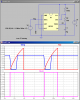
so if the 555 triggers when the trigger voltage reaches 33% of vcc would it trigger if i connect the trigger to ground? else how am i supposed to trigger it?

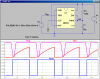
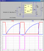
in the simulation the output = vcc from the beggining and it doesnt go to zero when threshold reaches 66% vcc and the capacitor doesnt start discharging..

please help..
ive attached the ltspice file

thanks :)
 

Attachments

  • Draft3..asc
    928 bytes · Views: 912
The circuit is all wrong, there's nothing to trigger it.

Compare your circuit, with the real 555 timer circuit and you'll see what I mean.
 

Attachments

  • 555 timer mono wr.PNG
    555 timer mono wr.PNG
    8.9 KB · Views: 3,043
isnt my circuit similar to what you've drawn? :confused: except for the control voltage connection which upto my knowledge is not neccesary.. and yes i havent connected the trigger so how do you trigger it in ltspice for simulation? please be kind enough to explain.. :) thankyou
 
isnt my circuit similar to what you've drawn? :confused: except for the control voltage connection which upto my knowledge is not neccesary.. and yes i havent connected the trigger so how do you trigger it in ltspice for simulation? please be kind enough to explain.. :) thankyou


Here is your circuit with some drafting enhancements, and with an added pulse generator which triggers the 555. Note that it takes a down-going signal on TRIG to cause the 555 to begin a timing cycle.
 

Attachments

  • Draft3..asc
    1.2 KB · Views: 980
  • Draft3...png
    Draft3...png
    32.6 KB · Views: 3,944
As an added note for your other thread, since the TRIG is a down-going signal, then the end of the output pulse from one 555 can be use to trigger the start of another 555 pulse.
 
Here is your circuit with some drafting enhancements, and with an added pulse generator which triggers the 555. Note that it takes a down-going signal on TRIG to cause the 555 to begin a timing cycle.
And, that trigger pulse has to be shorter in time than the 555 output pulse width.
 
Ah Roff, then my comment is not entirely correct. So you would have to connect the pulse from one 555 through a capacitor and pull-up resistor to properly trigger the next 555.
 
And, that trigger pulse has to be shorter in time than the 555 output pulse width.

If the TRIG input is longer than the 555 period, then the 555 becomes an "inverter", controlled by the Trig input crossing the 1/3Vcc comparator.
 

Attachments

  • Draft3...png
    Draft3...png
    32.9 KB · Views: 1,363
Don't mean to hijack this thread but how did you get the two seperate graphs in one screen?
Tried this but havn't got the right combo
 
don't mean to hijack this thread but how did you get the two seperate graphs in one screen?
Tried this but havn't got the right combo

Add Plot Pane under Plot Settings
 
Last edited:
oh thankyou guys :) things are a lot more clearer now.. one more question.. is it necessary for the trigger voltage to drop from vcc to below 33%vcc or can it be below 33%vcc from the begginning?
 
oh thankyou guys :) things are a lot more clearer now.. one more question.. is it necessary for the trigger voltage to drop from vcc to below 33%vcc or can it be below 33%vcc from the begginning?

Here you go: The threshold for the TRIG pin is 1/3Vcc (3V). The threshold for the THRS pin is 2/3Vcc (6V).

btw: another thing I noticed. Discharging a 25uF capacitor without limiting the current is bad practice. I added R2 to reduce the peak current. Doesn't change the timing.
 

Attachments

  • Draft3...png
    Draft3...png
    33.6 KB · Views: 903
Last edited:
btw: another thing I noticed. Discharging a 25uF capacitor without limiting the current is bad practice. I added R2 to reduce the peak current. Doesn't change the timing.
That's a good precautionary measure for most capacitor discharge circuits, but it's not required for **broken link removed**.
Code:
Note 7: No protection against excessive pin 7 current is necessary providing the package dissipation rating will not be exceeded.
This is probably true of all mfr's parts, but I couldn't find any mention of it in Fairchild's datasheet. I would think it would be in the datasheet if it could be a problem, but who knows?
 
i see.. thanks.. now im trying to make the end of the first pulse of the 555 trigger another 555.. this works but the problem is when i connect the output of the first 555 directly to the trigger of the second 555 the second triggers before the first because the output of the first is zero in the beginning..

ill upload the asc.. the second 555s output has two pulses.. nyway to limit that only to the last?


This is a likely artifact of how you are instructing LTSpice how to model the initial power-up. Possibly get rid of the STARTUP, and use the .IC statement to reflect the reality of the state of the timing capacitors after power-up.
 
Last edited:
I for one am glade you two are posting the LT SPICE files. I have picked up a few things here and there.
 
I mean like this.


Here is my way of triggering a second 555 from the first. I use a diode to clamp the positive spike.
 

Attachments

  • dual555.zip
    3.1 KB · Views: 377
Status
Not open for further replies.

Latest threads

New Articles From Microcontroller Tips

Back
Top