Continue to Site

Welcome to our site!

Electro Tech is an online community (with over 170,000 members) who enjoy talking about and building electronic circuits, projects and gadgets. To participate you need to register. Registration is free. Click here to register now.

  • Welcome to our site! Electro Tech is an online community (with over 170,000 members) who enjoy talking about and building electronic circuits, projects and gadgets. To participate you need to register. Registration is free. Click here to register now.

555 and 4017 led control

Status
Not open for further replies.

tim123

New Member
hi guys

i want to make a small led brightness controller, the leds are already in strips on a seperate board, runs of 12v at the moment.

a friend recommended that i look into pwm brightness control. i have done a bit of reading, and looked into control with a pic as well. i will have to control 2 sets of leds seperately, so the blue can be brighter at night and the white brighter during the day.

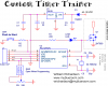
i had setup something like this..

555 timer -> 4017 -> (pin1: 400ohm) -> 555 timer pin 6
-> (pin2: 300ohm) ->
-> (pin3: 200ohm) ->

i had hoped that the different resistors on the 4017 outputs would change the timing amount on the 2nd 555.. in crocodile clips i could not get it to work.

any ideas guys?
 
tim123 said:
anyone?

also is pic goign to be easier.

tim.
Your text-based schematic doesn't do it for me - and I suspect that's why you haven't gotten any responses. If you have a Crocodile Clips schematic, you should be able to post it.
 
hi,

i have been playing around with c.c again, but can't figure out how to get a resistor coming from a pin on the 4017 to vary the timing on the 555 timer.

basically i want to use pwm brightness control on the LED, by having the 2nd 555 timer oscilate fast enough so the led is brighter/dimmer but not flashing. I was trying to do this by somehow affecting the timer circuit through the 4017 outputs.

I plan to have 8 steps on the 4017, each step 3 hours.. so the LED will vary brightness every 3 hours, and continue this cycle every day.

I hope its not too bad a schematic.. but you will hopefully understand where im going wrong, or if im just doing something thats completely impossible.

thanks.
 

Attachments

  • led555_4017.jpg
    led555_4017.jpg
    37.4 KB · Views: 3,039
An ordinary CD4017 Cmos stepper with a 5V supply has outputs that are about 1.2k ohm from either the positve supply (turned on) or from ground (turned off).
A 74HC4017 has outputs that might have a resistance that is about 100 ohms from either the positive supply or from ground.

The outputs of your CD4017 can supply base current to a transistor through a resistor and the transistor will have a very low resistance to ground when it is turned on.
 
I have had excellent results using CMOS analogue switches to change both
timing resistors and capacitors for 555 timers.
 
does the idea sound right though?

just trying to get out of buying all the pic equipment, and having to learn the programming. :)

thanks guys
 
k7elp60 said:
I have had excellent results using CMOS analogue switches to change both
timing resistors and capacitors for 555 timers.
Of course. An analog switch has a low resistance when turned on. A Cmos logic output isn't.
 
tim123 said:
does the idea sound right though?
I would use the high output resistance of a CD4017 to change the high resistance reference voltage of a triangle-wave-comparator PWM circuit, not the timing parts of a 555.
 
You won't be able to get a 3 hour period from an RC oscillator (555 or other), because of capacitor leakage. You will need a frequency divider or a microcontroller.
 
OK, i have started a circuit using the pic micro controller, just need to know whether its worth counting up to 3 hours within the pic, or use an external timing source (555 and 4017(s)) to count and provide an input to the pic..

i will let you all know how i get on.. any good tutorials you have seen regarding PWM from a pic?

thanks.
 
Simple Timer & LED with ICD2 connector for debugging

Here's my quick and simple schematic for a timer with a few options.

I've selected the 12F675 as it's cheap and has an A/D converter.

The best tool for learning and programming at the same time IMHO is a ICD2 or clone
 

Attachments

  • customtimer.png
    customtimer.png
    16.7 KB · Views: 1,243
OK, so i maybe if i do the counting in the pic, using lots of loops etc. I understand that the 16f627a has one PWM output, i plan to hook up a bc548 or simliar off the output, to drive a mosfet, which all of the leds will drive from.

could someone write me a basic code example, of how the PWM actually works. Just to turn the led on at a certain time at a specific brightness.

btw is there a basic programmer for the pics, i have found many basic compilers, but nothing which I can write my basic code into. I am not good at all with asm as many of you would have noticed.

cheers all.
 
ok the 16f88 sounds good.

is there a basic simluator that will show me the pwm output of the port?
the reason i ask is that i am told that its more difficult to do "if.. then.. else" statements within asm.

for those of you wondering i have attached the xls file in which i was hoping to base my pwm calculations from, 255 being full on, to 0 completely off.

I've read a fair bit of the asm tutorial now, can get an led to flash on an off.. still got a fair way to go by the sounds of it. if anyone has a spare few moments and wants to write some code to count the 8 sections of 24 hours (3 hour sections) and operate the pwm on the port (single color, i'll use a pic each for white and blue) i'd be very happy to get some code from you and try to learn it.

:)
 

Attachments

  • led_intensity_pwm.xls
    17.5 KB · Views: 274
Status
Not open for further replies.

Latest threads

New Articles From Microcontroller Tips

Back
Top