Electro Tech is an online community (with over 170,000 members) who enjoy talking about and building electronic circuits, projects and gadgets. To participate you need to register. Registration is free. Click here to register now.
Welcome to our site! Electro Tech is an online community (with over 170,000 members) who enjoy talking about and building electronic circuits, projects and gadgets. To participate you need to register. Registration is free. Click here to register now.
Hello all,
I am trying to design an LED driver circuit withan output of 70V,800mA. I tried the design with bridge rectifier but it was unsafe. How should I design the driver using SMPS which would comply with safety issues?
If you are having problems with the bridge rectifiers then this project is probably to complex.
Here is a very simple 25 watt non isolated example.
If you have questions please ask.
This is designed for 144 Volts at 175 mA constant current. With a modification I think it will work at 70 volts and 350 mA.
To learn about switch mode power supplies, this is a good place to start.
I got hold of a design using a link switch of Power Integrations and with the PI Expert Suite software, I got the following result. But I am having some problem understanding the circuit. What is the use of the circuitry before the bridge?
I got hold of a design using a link switch of Power Integrations and with the PI Expert Suite software, I got the following result. But I am having some problem understanding the circuit. What is the use of the circuitry before the bridge?
That looks to be a voltage regulator?, and not an LED driver like you're looking for - an LED driver needs to be a constant current, not a constant voltage (and that's not even a very good constant voltage - as it uses feedback from a separate winding).
I don't have time to look now. Some of these only voltage feed back to protect from over voltage. Some of the ICs are current in regulated. So they pull power off the line until they reach a certain current. Current in translates to current out.
This brand of IC has brothers that are Constant Current or Constant Voltage or Constant Power depending on which part number you order.
There doesn't appear to be any current sensing in the circuit, unless it's entirely inside the IC?, which would seem unlikely and make the IC far less useful.
About post #6
The LNK420 is not used for normal power supplies.
1) It has Power Factor Correction. There is no large storage capacitor after the full wave bridge. It takes power from the power line much like a restrictive load. During zero crossing of the power line it can not supply power to the load. This caused high 100/120 Hz ripple on the load. This is on purpose. It is fine for lighting but not good for normal power supplies. (light bulbs act like this)
2) The data sheet said it monitors the LED voltage but not really regulates it. The LED voltage can be 1.5:1 different from LED to LED and still work.
"provide a constant output current over a 2:1 output voltage range" it also regulates over a wide input voltage range. typical= from low line 110 to high line 220 there is 3% change in output current.
3) Dimmable. If the IC detects a dimmer is being used it reduces the output power by the duty cycle of the dimmer.
4) I think the IC is watching the secondary current by watching the primary current. I can see it is monitoring the primary current every cycle. I think it is monitoring the 70V but not regulating it. (watching for open circuit) It is watching the current every cycle. (66khz)
5) It has several different modes of regulation.
5a) There is the average current over 100mS which is to keep the light constant.
5b) There is the sign wave current at 50/60hz to make power factor correction work.
6) This part will shut down if he line voltage is too low or too high. It also will shutdown if the temperature is too high. Also if the LED voltage is not right. LED open or LED shorted.
Also I have a problem in understanding the terminologies of a transformer. I have a design but cannot understand the terms therein. Please help me with that.
There are instructions on how to build the transformer.
This power supply does not see the output directly. It looks at the "bias" winding which should look the same as the output winding. (just lower voltage) So the transformer is made so the first secondary and the second secondary winding are "closely coupled".
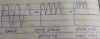
Speaking in raw terms, will the waveforms be like this?
And if the waveform is filtered,how would the transformer secondary work (as it works on ac only)?
It would be helpful if someone would tell the waveforms at different stages.
YES:
1)Power line is AC
2)The bridge output is half wave + half wave 100 or 120 hz all positive.
3)There is not much filtering here. There should be very little filtering because this is a PFC power supply.
Most (old) power supplies take power only from the very top of the sign wave. They store this power for the valley (or zero crossing). (the power company hates this) Current is very at the peak and zero most of the time.
This looks like a PFC supply which pulls power much like a resistor. The current flow is like it would be if a resistor was on the power line. (the power company likes this)
One end of the transformer has what you drew. (120hz half sign wave)
The other end is switches at 60khz or 120khz or what ever frequency the IC runs at.
>>When the IC pulls the transformer to ground (there will be the power line voltage across the transformer).
>>>>The power line voltage changes at 120hz. It will be any there from the very peak to zero volts.
>>Then the IC opens up the transformer will "fly up" above the power line voltage.
>>>>>The transformer will fly up to a level there power goes out the secondary.
>>Then three is likely a dead time there no voltage is across the transformer.
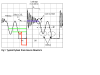
The voltage across the transformer will look like this: Frequency=100khz.
There is a line "Vin" that is "0" volts. When the IC is on the line voltage is across the transformer (negative voltage)
Black is typical.
Red is for then the line voltage is high.
Green and green are when the voltage is low.
For now don't think about the "leakage inductance ring", Just think of the voltage as the blue line. This is when power is sent to the load. The distance from "0" to blue will be the same at high Vin or low Vin.
The time after "core reset" where there is low frequency ring is call dead time. Nothing is happening. No current flows.
But I am not getting this. If I have used a full wave rectifier and removed the negative part of waveform, how will I get it at the primary of the transformer? For that, the current should flow in reverse direction but there are two diodes, so that is not possible. So how are we getting the negative peak?
Please help...
This site uses cookies to help personalise content, tailor your experience and to keep you logged in if you register.
By continuing to use this site, you are consenting to our use of cookies.