Continue to Site

Welcome to our site!

Electro Tech is an online community (with over 170,000 members) who enjoy talking about and building electronic circuits, projects and gadgets. To participate you need to register. Registration is free. Click here to register now.

  • Welcome to our site! Electro Tech is an online community (with over 170,000 members) who enjoy talking about and building electronic circuits, projects and gadgets. To participate you need to register. Registration is free. Click here to register now.

4X4 KEYPAD TO 16 RELAYS HELP!

Status
Not open for further replies.

egg0900

New Member
I AM TRYING TO ACTIVATE 16 RELAYS WITH A 4X4 KEYPAD MEMBRAIN AND I AM TRYING TO ELIMANATE THE USE OF 4 SETS OF 9 VOLT BATTERIES. I WOULD LIKE THIS TO COME FROM ONE POWER SORCE OF 9 VOLTS
 

Attachments

  • circuits.jpg
    circuits.jpg
    109.4 KB · Views: 614
There is a solution without active elements but it aint pretty ;-)

It requires eight 4-pole relays. Just take a look at the keypad topic
(look for the second version of keypad matrix):

https://www.electro-tech-online.com/threads/digital-tuning-radio-interface-with-lcd.6615/

Make sure to remove R8 (put short) and replace other resistors with relays. Each output will require two relay contacts in series.
Since each button will turn on two relays (the coils will be in series)
power supply should be for ca double of the coil ratings.
Single 9V battery should work with 5V relays.
 
Last edited by a moderator:
hi egg0900,

i had exactly this problem with an old teletype
some years ago .....

the keyboard was matrixed up as eight by eight
and the elecromechanical letter solenoids were
also matrixed up eight by eight.

i finally got the keyboard to operate the letter
solenoids with a weird setup of capacitors and
resistors, i will try to dig out the details,
and see if it could apply to this .....

meanwhile ...
if you could be happy with only two batteries,
i sort of feel you could halve the matrixing
by feeding through two diodes, but i haven't
thought it through yet, but give it a think ...

i will come back on this,
John :)
 
Hi egg0900,

I think Sebi is correct,
you will need some active elements to do this.
I am surprised at the lack of response to this thread.

I have not given the possibility of two batteries
and diodes much thought,

but i did come up with this possibility instead.
The transistors used would be four PNP and four NPN.
They don't need to be 'matched' just similar.

The resistor values are just guesswork, maybe the
middle resistors could be a bit higher.
But they should work ok as shown, i think.

As shown, a little current would also travel in
adjacent relays when one is operated, but it wont be
much.
If that bothers you, you could fit diodes on each relay.

I don't know what operating current your relays are,
you would have to choose appropriate transistors.
Notice that two transistors in series operate each
relay, so the transistors have to be good enough to
do that.

I hope this will meet your needs, regards John :)
 

Attachments

  • relay_matrix.jpg
    relay_matrix.jpg
    32.2 KB · Views: 520
Hi egg0900, and anyone else looking in,

I've just received a PM from 'egg0900',
he says the relays he's using are 5 volt,
so if they are little iddy bitty ones,
then they might operate ok on about 300mA or less,
in which case something like BC108 should be ok
and a similar for the PNP ones.

If you reply back to the thread, then more people
get to see it, and could suggest helpful alternatives,
but i do appreciate the reply.

I would be interested if anyone could suggest
suitable transistors or resistors ?
Or maybe a completely different circuit ?

If the relays are very small,
it's possible they could be driven straight from TTL,
which might make for a simpler construction ?

Best of luck with it,
Regards, John :)
 
john1, Your circuit is pretty. Maybe if we know, for what application need this conversion, we can give more help. E.g.: if need only the conversion from matrix keys to 16 outputs with common GND, optocouplers also a solution with lower price...
 
This is the same circuit without active components:
 

Attachments

  • matrix.gif
    matrix.gif
    11.8 KB · Views: 438
Hi Sebi,

Thank you for the compliment.
Your point about the common ground is well taken.
If the relays needed a common ground,
then clearly that circuit would not do.
However in the first post it looks like
a common ground was not needed.

Best Regards, John :)
 
Hi panic mode,

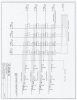
That circuit looks very interesting,
but i can't quite follow it,
maybe theres some missing ?

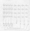
It sort of reminds me of that circuit i made years ago,
to match a set of teletype letter-solenoids with their
keys on a keyboard, that was just resistors and
capacitors.

But for the teletype it only had to operate the letter-
solenoids briefly, just for about half a second or less
as i recall, so the circuit i came up with for that
would not do for this.
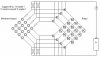
Basically it was the same as the one in the first post,
but i had caps where egg0900 has batteries, they were
fed by resistors from the supply, pressing a key
discharged a cap into a letter solenoid.
8x8 keyboard, 8x8 solenoid board, the hardest thing was
the wiring!

Please give some explanatory notes on that diagram,
i am finding it confusing !

John :)
 
4x4 Relay project other half...........fun! :)

The realys used are 8 pin two different inputs one from original membrane
one from 5vdc to be switched and sent threw resistors to a adc chip. :p :p
 

Attachments

  • 4x4_membrane_2.jpg
    4x4_membrane_2.jpg
    126.9 KB · Views: 484
hi john,

I tought this is self explanatory but let me try to explain.
The drawing was done in hurry so I left the switches out
because they are integral part of the 4x4 matrix.
So there are 16 of them (4x4=16) and they are wired to
intersections of rows and colums. For example membrane
switch in upper left corner of the matrix is connected to A2
terminal of R5 coil and A1 terminal of R1 coil.
Vertical line connected to A1 of R5, R6, R7 and R8 is positive
rail (+9V for example). A2 terminals of R1, R2, R3 and R4 are
connected to negative rail (0VDC for example).
When first membrane sw. ("0") is pressed, current flows from
positive rail through R5, through switch and through R1.
Yes, R1 and R5 coils will be in series.
If you want 9V power, use 5VDC relays because coils are in series.
To control something, just use contact of each relay in series like
the first branch in the upper right corner.
You have there pair of terminals going to whatever you want to
control. Between the terminals you have contacts from R1 and R5.
So button "0" will activate R1 and R5, and output "0" has contacts from R1 and R5 in series.
So button "0" will activate R1 and R5.
Output "0" has contacts from R1 and R5 in series.
Button "1" will activate R1 and R6.
Output "1" has contacts from R1 and R6 in series.
Button "2" will activate R1 and R7.
Output "2" has contacts from R1 and R7 in series.
Button "3" will activate R1 and R8.
Output "3" has contacts from R1 and R8 in series.
Button "4" will activate R2 and R5.
Output "4" has contacts from R2 and R5 in series....

I hope this explains it. This is not the silver bullet for matrix keypads.
Scanned matrix is much better of course because there are no
problems when multiple buttons are pressed. I've posted it simply
to demonstrate that it is possible to make circuit without active
components.

8)
 

Attachments

  • matrix2.gif
    121.2 KB · Views: 455
Status
Not open for further replies.

Latest threads

New Articles From Microcontroller Tips

Back
Top