Continue to Site

Welcome to our site!

Electro Tech is an online community (with over 170,000 members) who enjoy talking about and building electronic circuits, projects and gadgets. To participate you need to register. Registration is free. Click here to register now.

  • Welcome to our site! Electro Tech is an online community (with over 170,000 members) who enjoy talking about and building electronic circuits, projects and gadgets. To participate you need to register. Registration is free. Click here to register now.

4Moms MamaRoo 4.0 - Identify this sensor?

Status
Not open for further replies.
The tests that you have just done shows that the diode on the module is OK. (The 0.682 reading is the forward voltage drop (In volts.) in the direction when it is conducting. With the negative lead on pin 3 and the positive lead on pin 4 the reading MAY drop if you shine a bright light on the sensor. A better test would be to power the unit up and the meter set to the 20 volt DC range You should get a reading which should drop when yo shine a bright light on the sensor. As we know that the IR emitter is not working I think the doing the following tests would be more useful. With the negative meter lead still on pin 3 measure the voltage on pin 1 (This is the power supply to the IR emitter.) Also measure the voltage on the two lower pins of the sensor (With the negative lead still on pin 3.)
These tests will show if the IR emitter is not working due to no power to it or the IR emitter is either short circuit or open circuit.

EDIT These comments were in response to post #38. ( I have now seen that there have been more posts since I started typing my reply.)
Les.
 
Hi Les,

Thanks for the instructions.

I have followed what you have suggested, I think, and below are the results I got from these tests:

With the negative lead on pin 3 and the positive lead on pin 4 the reading MAY drop if you shine a bright light on the sensor.
- to pin 3, + to pin 4 = 0.61v, bright light = 0.61v

A better test would be to power the unit up and the meter set to the 20 volt DC range You should get a reading which should drop when yo shine a bright light on the sensor. As we know that the IR emitter is not working I think the doing the following tests would be more useful. With the negative meter lead still on pin 3 measure the voltage on pin 1 (This is the power supply to the IR emitter.)

- to pin 3, + to pin 1 = 11.04v

Also measure the voltage on the two lower pins of the sensor (With the negative lead still on pin 3.)

- to pin 3, + to pin 4 = 0.61v
- to pin 3, + to pin 2 = 0.00v

I also decided to check the voltages across the 4 pins for the wires coming to the board, let's call them A, B, C & D.

A= 11.04v
B= 3.29v
C= 0.00v
D= 0.60v

Not sure if this helps any? Photo attached...
 

Attachments

  • 20201101_155444.jpg
    20201101_155444.jpg
    196.7 KB · Views: 262
Last edited:
I don;t understand your statement " I also decided to check the voltages across the 4 pins for the wires coming to the board, let's call them A, B, C & D."
Across implies between two points but each line only gives one point. So the readings must be with respect to some unspecified reference point; This does not really matter as i was interestes in the voltage on the lower two pins of the sensor chip. The pin numbers you used do not seem to match the numbering shown on page 2 of the datasheet that Pommie provided the link to in post #5. Assuming that you did do the measurements to the lower two pins on the sensor chip the IR emitter has failed. The voltage difference between them should be about 1.2 volts. (You measured 0.6 volts.) As you have checked the value of the 820 ohm resistor and the voltage on the positive end of it, it is the sensor that need replacing. I suggest cutting the legs of the chip close to the body with small side cutters and then un-solder the remains of the legs one at a time to reduce the risk of damaging the board.

Les.
 
The tests really suggest the emitter is bad. I'm suggesting that the emitter could be damaged by the act of putting a (V battery into the module (I'm assuming a 9V battery). It's easy to briefly connect the battery briefly to the wrong polarity. So, it's a design problem.

I didn't see a link for the datasheet. With a datasheet, I can confirm the reverse voltage spec of the LED. (I'm assuming 5-6 V). Since it's a common problem, it might be reported to the manufacturer with the fix.

e.g.
A member of an electronics forum where I have had the discussion of the failure of "your product" suggested that The LED emitter on the motor sensor could possibly be damaged by putting a battery into the product. While fiddling with the 9V battery connector, you can accidently apply a reverse polarity. Per the datasheet https://components101.com/sites/default/files/component_datasheet/IR LED datasheet.pdf (not the right one), Vf or max Reverse voltage is 5V. (9v is too high. This is a guess of the sensor p/n. Mosr LED have a Vr around 5V.

Since many people are having the same problem, the following design change was suggested by the forum member.
Add a diode (1n4001) and resistor (value) for the 820 ohm resistor. This can be retrofitted on existing products.

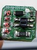
EDIT: Looking at the nice pretty picture in post #42, it might be possible to add an SMT diode,by scraping the green pad on the left and removing some material and butt the resistor and diode together and glue it in place.

Electronic grade silicone which has no acetic acid or superglue.

Also see: https://www.ti.com/lit/an/slva139/slva139.pdf


==

The light test would only work if the light source has a significant amount of IR, An incandescent light MAY work. A plastic lens will filter the IR. A flame would have some IR as well.

We used ELH lamps and we had to buy a particular manufacturer's ELH bulb because of the spectrum. Sylvania was different than GE. The lamps have a dichroic filter that puts most of the IR out the back of the lamp. The lamp has a parobolic reflector built in.

To fix that, I will suggest getting a thru-hole resistor (defined earlier) and 1n4001 diode. take out the 820 ohm resistor and replace it with a network of a resistor and a 1n4001 diode.

The 0.6 V that you are seeing is the general range of the voltage drop across a good diode. Shotkey diodes can get this voltage down to about 0.2V. This voltage drop is dependent on temperature. Diodes can be used as a temperature sensor once calibrated at one point usually.

The 1 is the indication the meter uses for "out of range". Should be the same thing for test leads open on the ohms range. Some meters read in mV. LEDs have a high voltage drop and the diode scale may not work with all meters The voltage drop depends on color.

I did use a circuit using a few MOSFETS that has a much lower voltage drop. See https://www.ti.com/lit/an/slva139/slva139.pdf

Adding a 0.6V voltage drop to the entire circuit at the battery connector would work, but would cut down on run-time. This one is0;.4V at 1A (guess the current of the motor).

Cutting the leads is the suggested method of removal of multi-pin devices that you know is bad.

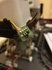
The emitter side is definitely bad. Adding a diode and changing the value of the 820 ohm resistor can protect the emitter against reverse polarity. it might be possible to do with an SMT diode. I didn;t yet look for a possible replacement. We need the pic of the board taken with a ruler or something of known dimensions in parallel with an edge or what your trying to measure. A dime would even work.


reverse polarity protection is recommended for the entire circuit. For that, we need more information. e.g. Full load amps for the motor and circuitry. Report design changes to manufacturer.
 
Last edited:
I don;t understand your statement " I also decided to check the voltages across the 4 pins for the wires coming to the board, let's call them A, B, C & D."
Across implies between two points but each line only gives one point. So the readings must be with respect to some unspecified reference point; This does not really matter as i was interestes in the voltage on the lower two pins of the sensor chip. The pin numbers you used do not seem to match the numbering shown on page 2 of the datasheet that Pommie provided the link to in post #5. Assuming that you did do the measurements to the lower two pins on the sensor chip the IR emitter has failed. The voltage difference between them should be about 1.2 volts. (You measured 0.6 volts.) As you have checked the value of the 820 ohm resistor and the voltage on the positive end of it, it is the sensor that need replacing. I suggest cutting the legs of the chip close to the body with small side cutters and then un-solder the remains of the legs one at a time to reduce the risk of damaging the board.

Les.
Hi Les,

Yes, sorry, it doesn't make much sense when I read it back to myself again either...

I set the negative wire of the multimeter into the headphone jack and then the positive wire on the multimeter to each of those points A, B, C & D and got those voltage readings...

But, as you have confirmed it's irrelevant as you confirmed the IR emitter has the failure.

I have ordered a replacement but I'm not overly confident of doing the solder work myself, it is very miniature...

I might look around the net to see if I can find someone here in Ireland that would be willing to give it a go without robbing me blind.

When it arrives I may reconsider doing it myself but it's daunting to say the least and I could just end up causing more damage.

Thanks again for the help!!

Cheers,
Mac
 
I am currently doing a project using the **broken link removed** I posted a link to earlier. I'm using a 5V supply but much should be the same. I used a 220R resistor to limit the LED current = 16mA (I think yours is ~10mA). I used a 47K resistor in the collector and with no reflection got >4.9V at the collector of the receiver (transistor fully off). With a piece of white paper 1mm away from the reflector it read <0.5V (transistor fully on).
This was the circuit,
opto.png

Are you able to trace your circuit to establish if it is similar? Are the other two opto boards identical to the not working one? Are you confident enough to put a working board in place of the broken one and take some readings?

Note, I posted the above opto sensor as an example only - it's unlikely the correct one but may help identify the one you've got.

Mike.
Edit, note that in the datasheet the diagonally opposite pins (emitter and cathode) are grounded which appears different to yours. The pin numbering is also different to what has been used on this thread.
Edit2, just changed the 47K for a 100k and the results stay the same, showing it's not critical in a black/white situation.
 
Last edited:
Hi guys,

Just an update on this.

My replacement sensor came this afternoon and I decided to tackle it myself. It was quite daunting and I'm confident my soldering job wasn't great but the replacement sensor is working perfectly.

The IR light is a slightly different colour so I was a bit sceptical that it would work but all is good.

Thanks so much to everyone who helped, great support on this forum.

Cheers,
Mac
 

Attachments

  • 20201107_173838.jpg
    20201107_173838.jpg
    1.3 MB · Views: 278
I showed your thread to a former 4Moms engineer. He I s impressed that the team here solved it and a rookie managed to implement it and get it working. He is cringing about how this impacts product safety but hey - it was defective and likely unsafe in the first place. Good work everyone.
 
I showed your thread to a former 4Moms engineer. He I s impressed that the team here solved it and a rookie managed to implement it and get it working. He is cringing about how this impacts product safety but hey - it was defective and likely unsafe in the first place. Good work everyone.
Well, I guess I didn't make it any less safe... If I messed up the soldering it would probably just need another sensor purchased...

It cost me £4 UK pounds for the fix, a slight bit better than what 4Moms were willing to offer me at £60 UK pounds... Maybe the engineer should mention that too :)

Anyway, all is good. Thanks again everyone...
 
Where did your order the replacement part? I have one probably with the same issue and would like to try fixing it. Thanks.
 
Where did your order the replacement part? I have one probably with the same issue and would like to try fixing it. Thanks.

Hi there,

I bought it off eBay in UK to save having to pay import duty:


But, before you go ordering you can test if it's this sensor easily by using your phone.

Plug it it, power it on and then open the camera app on your phone. You should see a light coming off that wee sensor if it's working.

There are 3 of these sensors on the cradle, check all 3.

Cheers,
Mac
 
Thanks! I just did that and I do see light coming off all 3. I'm wondering if it could be the sensor instead of the emitter that is the problem.
 
Thanks! I just did that and I do see light coming off all 3. I'm wondering if it could be the sensor instead of the emitter that is the problem.

Hi there,

It's probably unlikely but it's hard to know...

What is happening on the display that has it not working? Is it showing any message or blockage message?

Cheers,
Mac
 
Just the typical obstruction error. I fixed it before by repainting the wheel and blowing dust out, and usually it'll be good for a good while but now it just gets the obstruction error within 3 or so seconds and my past solutions aren't working anymore.
 
If you have a multimeter you could step back through this thread and do the tests that the lads posted for me to check if mine was dead and you might be able to determine if the receiver part of the sensor is dead perhaps...

It's beyond my knowledge but it's worth a shot!!

Cheers,
Mac
 
Status
Not open for further replies.

Latest threads

New Articles From Microcontroller Tips

Back
Top