Continue to Site

Welcome to our site!

Electro Tech is an online community (with over 170,000 members) who enjoy talking about and building electronic circuits, projects and gadgets. To participate you need to register. Registration is free. Click here to register now.

  • Welcome to our site! Electro Tech is an online community (with over 170,000 members) who enjoy talking about and building electronic circuits, projects and gadgets. To participate you need to register. Registration is free. Click here to register now.

4Moms MamaRoo 4.0 - Identify this sensor?

Status
Not open for further replies.
Pinout

E358F370-48BD-4223-B141-57C6D8EED412.jpeg
 
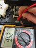
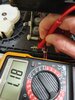
if you have a multimeter, measure in ohms by touching solder pads 1 and 2 and hopefully you'll measure 820 ohms. If not, measure 1 to 3 (I cannot be sure where which pad (2 or 3) the copper trace connects below the proximity sensor).

if you get infinite resistance both ways, either the resistor or the solderjoints on the resistor are bad.

also, double check that the solder under pad 1 in my photo is a good solder joint.

View attachment 127746

So, measuring the resistance between pins 1 & 2 give me 820 ohms so does that mean the resistor is fine?

Anything else to check?

Thanks,
Mac
 
Last edited:
So, measuring the resistance between pins 1 & 2 give me 820 ohms so does that mean it's fine?

Anything else to check?

Thanks,
Mac
Yes, the resistor is ok unless something strange is happening with heat causing it to disconnect when it gets warm (unlikely so let's move on).

if you have a 9v battery, connect positive to my red 1, and negative (black wire) to the cathode (across the part form red 2. Then measure voltage from red 2 to the cathode and report back. Hopefully it is between 0.8 and 1.8v.
 
Apply + of 9v where it says 9v, - of 9v to red 2
Then measure voltage from 1 (red test lead) to 2 (black test lead).
B3521819-A172-43ED-B5A2-FEEC7AFD065E.jpeg
 
befor replacing any components on the board I suggest doing the following . From the picture in post #18 this is my understanding of the connections to the board. Counting from the bottom. I think the fists connection is the positive supply to the IR emitter. The next one up is the positive supply to the sensor. the third connection is ground and the top connection is the sensor output signal. Can you get a positive voltage with respect to ground on the bottom two connections . (An post the value of these voltages.) Connect you meter between ground and the top connection. With nothing reflective in front of the sensor the voltage reading should be a bit less than the reading you measured on the next to bottom connection. Now if you place something reflective (White paper or reflective metal.) a few mm from the sensor the reading should drop to close to zero. If this happens the board is working. You could then do this test with the sensor in it's original position and note the readings when the white part of the encoder disk is in front of the sensor and when the black part of the encoder disk is in front of the sensor. post the voltage readings. The function of the sensor is to detect the wite and black positions of the disk.

Les.
 
If this happens the board is working.

Hi Les,

Thanks for the good suggestion, appreciated.

I think at this stage I'm pretty certain that this sensor board is faulty but just not certain which component on the board is to blame.

The reason I'm pretty certain is the the wee sensor isn't emitting an IR light. The cradle has three such sensors and this one is the only one not showing any IR light.

It might be a very valid test in other circumstances, perhaps worth knowing anyway that the pins are as you have described.

I need to go get a 9V battery and carry out that other test that was described just before yours.

Thanks a million though, I'll get to bottom of this yet will all this great advice!!

Cheers,
Mac
 
After seeing the suggestion that you use a digital camera to check the emitter I just scanned through the following posts when I saw the pictures showing the infra red emitter working. I did not read the text so assumed it was the suspect sensor board. Before replacing the 820 ohm resistor I suggest checking the voltage on the bottom pin of the board and between the two bottom pins on the sensor chip.

Les.
 
Apply + of 9v where it says 9v, - of 9v to red 2
Then measure voltage from 1 (red test lead) to 2 (black test lead).View attachment 127748

Hi there,

Sorry for the delay but I had to pop to the shops for a battery to to test this and only back now.

From pins 1 to 2 the 9v (9.6v to be precise...) carries across fine. If I go from pins 1 to 4 then the output at pin 4 is roughly 3v by time it passes the sensor.

Anything else to try with this approach?

Thanks,
Mac
 
After seeing the suggestion that you use a digital camera to check the emitter I just scanned through the following posts when I saw the pictures showing the infra red emitter working. I did not read the text so assumed it was the suspect sensor board. Before replacing the 820 ohm resistor I suggest checking the voltage on the bottom pin of the board and between the two bottom pins on the sensor chip.

Les.

Hi Les,

No worries, I will check that in a bit.

We checked the actual resistor earlier in the thread and it was showing the correct ohms so I suspect it is working ok.

At this stage it looks like the wee sensor itself that is faulty.

I will check it later and report back.

Thanks,
Mac
 
Then you can plug in the unit,
Hi there,

Sorry for the delay but I had to pop to the shops for a battery to to test this and only back now.

From pins 1 to 2 the 9v (9.6v to be precise...) carries across fine. If I go from pins 1 to 4 then the output at pin 4 is roughly 3v by time it passes the sensor.

Anything else to try with this approach?

Thanks,
Mac

I hope you didn't hold the battery across pins one and two. It should be from the 9v (positive) to pin 2 (negative battery terminal). Then measure with your volt meter the voltage across pin one and pin 2 while the battery is connected. You can damage the IR led if you connect it directly.
 
Finally, if you can get someone to help you, we can check the detector side - you'll definitely need one or two extra pairs of hands to do that.
 
Then you can plug in the unit,


I hope you didn't hold the battery across pins one and two. It should be from the 9v (positive) to pin 2 (negative battery terminal). Then measure with your volt meter the voltage across pin one and pin 2 while the battery is connected. You can damage the IR led if you connect it directly.

Hi there,

No, battery connected as you instructed above, + to where you stated 9v and negative to pin 2.

I then used the multimeter to test from pin 1 to pin 2 which read 9v. I then tested from pin 1 to pin 4 with the multimeter and it read around 3v.

Cheers,
Mac
 
What could make it die, is if the battery is 9V, it's possible to connect a 9V battery briefly backwards.

A diode with a low voltage drop in the main power or even one in series with the emitter portion of the sensor.

You could remove the 820 ohm resistor and use wires to an 820 ohm resistor in series with a diode. We can also resize that resistor to compensate for the voltage drop.

(9-0.6)/10e-3 = 840; 10 mA

So R=(9-2*0.6)/10E-3 <= 780 ohms (normal diode e.g. 1n4001)
Whatever us the closest 5% value; 1/4 W should work

The band on the diode should face the same way as the schematic symbol. Toward (-).
 
Last edited:
Finally, if you can get someone to help you, we can check the detector side - you'll definitely need one or two extra pairs of hands to do that.

I could get someone to give me a hand tomorrow if you were able to instruct me?

Are we trying to determine if sensor is faulty now or we checking other components?
 
if you have a 9v battery, connect positive to my red 1, and negative (black wire) to the cathode (across the part form red 2. Then measure voltage from red 2 to the cathode and report back. Hopefully it is between 0.8 and 1.8v.

I'm not sure I did the checks correctly after reading this again

I had the battery+ connected to the 9v on your diagram, the battery - to pin 2. I then had the multimeter red to pin 1 and multimeter black to pin 2. For this I was getting 9.6v.

I'm not sure what you suggested for the second part, red 2 to the cathode? I'm not sure which is the cathode pin?

Thanks again,
Mac
 
I'm not sure which is the cathode pin?

Cathode is minus, or the direction the arrow points to. If youbcan think of current flows from (+) to (-) in the direction of the arrow.
It is the band side of the diode.

red to pin 1 and multimeter black to pin 2. For this I was getting 9.6v.

This would indicate an open circuit.

If you have a multimeter with a "diode test" which will basically read a voltage drop and beep when it's low..
no power
- of multimeter on pin 3
+ of multimeter on pin 4
It should indicate OL or something out of range.

then shine a bright light like an incadesent flashlight the voltage drop indicated would get lower.
 
If you have a multimeter with a "diode test" which will basically read a voltage drop and beep when it's low..
no power
- of multimeter on pin 3
+ of multimeter on pin 4
It should indicate OL or something out of range.

Hi there,

Thanks for the explanation, very useful...

I have set up my wee cheap ass multimeter to what I think is the diode test, image attached?

Anyway, when I switch the multimeter on with this setting it shows 1 on the screen.

When I put the negative lead of the multimeter to pin 3 and then the positive lead to pin 4 it doesn't change, it stays at 1 on the multimeter.

If I reverse the + / - then it shows .682. Sorry, I've no idea what I'm doing here really..

I haven't connected this sensor to any power at this stage, sitting unplugged.

Any help greatly appreciated
 

Attachments

  • 20201101_122612.jpg
    20201101_122612.jpg
    1.4 MB · Views: 178
Hi folks,

I decided to measure the voltage over a working sensor and this faulty one to compare the values.

On a working sensor, the input voltage was coming in at 9.52v. When I tested it at the other side of the resistor it was showing as 1.18v.

Now I did the same test for the faulty sensor. The input was 11.04v and at the far side of the resistor it is still 11.04v.

Does that still mean the resistor is faulty and not reducing the voltage?

Perhaps the high voltage got across the resistor and then damaged the IR sensor?

Sorry for the poor photos, I was on my own trying to test this and take the photos...

Cheers,
Mac
 

Attachments

  • 20201101_124647.jpg
    20201101_124647.jpg
    1.5 MB · Views: 158
  • 20201101_124700.jpg
    20201101_124700.jpg
    1.5 MB · Views: 174
  • 20201101_124754.jpg
    20201101_124754.jpg
    1.8 MB · Views: 144
  • 20201101_124800.jpg
    20201101_124800.jpg
    1.9 MB · Views: 168
No, it means the LED is open and drawing no current. No current draw through a resistor means no voltage drop across the resistor.
 
Status
Not open for further replies.

Latest threads

New Articles From Microcontroller Tips

Back
Top