Continue to Site

Welcome to our site!

Electro Tech is an online community (with over 170,000 members) who enjoy talking about and building electronic circuits, projects and gadgets. To participate you need to register. Registration is free. Click here to register now.

  • Welcome to our site! Electro Tech is an online community (with over 170,000 members) who enjoy talking about and building electronic circuits, projects and gadgets. To participate you need to register. Registration is free. Click here to register now.

4Moms MamaRoo 4.0 - Identify this sensor?

Status
Not open for further replies.

mcquaim

Member
Hi there,

I'm not sure what is allowed here or what details should be posted but my sister gave me her 4Moms MammaRoo 4.0 baby cradle to look at as it's stopped working.

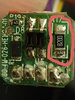
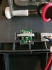
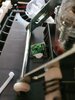
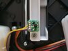
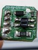
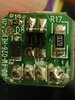
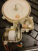
After a bit of investigation I've narrowed it down to a little sensor that monitors a wheel rotated by a small motor. The wheel is black with white segments painted onto it. This sensor must monitor these white segments and if the wheel stops turning it then cuts power to the motor.

From a bit of research this sensor appears to give a lot of problems and so many reports of ways to fix etc. Ideally I'd like to just bypass the sensor, I don't see the point.

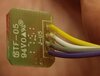
I'm wondering if the 4 wires might even be able to be joined to just allow the motor to keep running.

If it can't be bypassed then I'm wondering if they can be purchased anywhere?

I've attached the photos of the sensor. Any help would be greatly appreciated.

Thanks,
Mac
 

Attachments

  • 20201029_203031.jpg
    20201029_203031.jpg
    123.4 KB · Views: 533
  • 20201029_203054.jpg
    20201029_203054.jpg
    96.5 KB · Views: 526
  • 20201028_213423.jpg
    20201028_213423.jpg
    1.6 MB · Views: 431
Last edited:
It appears to be the sensor that turns off the motor if something/someone stops the motion of the rocker. That way, the motor won't burn out and decreases risk of overheating/fire of an electric device that an infant human is strapped into. I recommend not bypassing it.

you can try contacting 4Moms, a Pittsburgh PA company.

Also, it is a smart power pack - it will play music and "power up" but not rock unless you use the original power supply.

https://www.4moms.com/products/mamaroo-replacement-power-cord

 
Thanks for the reply.

I have sent 4Moms an email to see if that sensor can be bought but buying a whole base would be too costly...

I would be interested to try and bypass the sensor just to see if it was a faulty sensor though and it would run fine otherwise...

I just don't understand why it has 4 wires instead of just two?

Cheers,
Mac
 
Looks like the sensor is a photo sensor. An LED shines onto the disk, and a photo transistor sees the reflections from the light segments on the disk.

The controller may use the pulse stream to determine speed, so it's probably not possible to (easily) bypass this sensor.
 
Here's the datasheet to a similar **broken link removed**. You can test it by looking at it with a camera (phone) to see if one side is lit. You can then measure the voltage across the two opposite pins and see if it varies when you place something white in front of it. It could just be that the disk is not as bright as it used to be.

Mike.
 
Looks like the sensor is a photo sensor. An LED shines onto the disk, and a photo transistor sees the reflections from the light segments on the disk.

The controller may use the pulse stream to determine speed, so it's probably not possible to (easily) bypass this sensor.

Hi there,

I think you might be correct.

The motor can be set to speeds 1-5 so it's likely that this might control that.

I see the next post has a datasheet for the sensor itself so I might get more information from that.

Thanks,
Mac
 
Here's the datasheet to a similar **broken link removed**. You can test it by looking at it with a camera (phone) to see if one side is lit. You can then measure the voltage across the two opposite pins and see if it varies when you place something white in front of it. It could just be that the disk is not as bright as it used to be.

Mike.

Hi Mike,

Thanks for your post, it is very helpful.

I will try looking at it via the phone later, nothing is noticeable via the naked eye anyway.

I will report back with any findings.

Cheers,
Mac
 
There doesn't appear to be any light emitting from the wee sensor anyway

I'm not able to upload the little video clip on here...
 
New camera phones and cameras have ir blocking. You can take the camera apart to remove the IR filter (the Raspberry pi camera is easy). Or you can just buy the No-IR version of the pi camera if you want to experiment.
 
Thanks guys,

Would a FlirOne IR camera attachment for the phone pick it up?
No, flir cameras get 7um to 14um wavelengths. These are typically 850 to 950 range.
If you have a lab power supply or a battery and some resistors, I can walk you through the process of testing the IR diode and the photodetector (photo diode or phototransistor). A good multimeter (Fluke 87) in diode mode could is also helpful - specifically, diode mode that can go well over 1 V.
 
Hi folks,

I haven't gotten to test any further this evening but I came across this video on YouTube:


It looks like this is the same issue I'm having but I'm finding it hard to understand this video.

Does anyone know if this would be correct?

Also, would these be the correct replacement resistors?

**broken link removed**

Cheers,
Mac
 

Attachments

  • 20201030_204321.jpg
    20201030_204321.jpg
    122.7 KB · Views: 352
Hi folks,

So, after a bit of investigation this morning I can confirm that this wee sensor is faulty.

I used my phone on the other two similar sensors on the machine and they actually do light up where this one doesn't.

On my previous post I linked a YouTube video of some guy posting the same findings and he suggested replacing the wee resistor to the side fixed it for him.

I'm not sure if my soldering skills would be up to this job so I might look around to see if some local company might be able to replace it for me.

Could anyone confirm if those resistors I linked above are the correct ones?

Thanks again for all the help

Cheers,
Mac
 

Attachments

  • 20201031_111207.jpg
    20201031_111207.jpg
    1.4 MB · Views: 570
  • 20201031_111746.jpg
    20201031_111746.jpg
    1.8 MB · Views: 470
  • 20201031_111046.jpg
    20201031_111046.jpg
    3 MB · Views: 521
Although photos of solder can be mis-leading, it appears to me that the solder is very poorly placed on R17 (near the 7 of R17 text). You can take a soldering iron, heat it up. Wipe the iron across a fairly damp sponge several times to clean the tip, wait 5 to 10 seconds for the iron to get back to temperature, and touch the iron to that resistor edge AND the little pool of solder next to it at the same time). In just 2 to 4 seconds, you should see the solder flow up the side of the resistor and then remove the iron. Don't heat too long, if nothing happens in 5 seconds, repeat but at a little solder as you heat.

before you start, you can take some more photos at a better angle to confirm for yourself that the solder is not well placed.
 
Hi there,

Thanks for the reply.

I tried to take a better picture in better light but I'm not sure if the solder is that bad?

What do you think?

Thanks,
Mac
 

Attachments

  • 20201031_122255.jpg
    20201031_122255.jpg
    194 KB · Views: 294
if you have a multimeter, measure in ohms by touching solder pads 1 and 2 and hopefully you'll measure 820 ohms. If not, measure 1 to 3 (I cannot be sure where which pad (2 or 3) the copper trace connects below the proximity sensor).

if you get infinite resistance both ways, either the resistor or the solderjoints on the resistor are bad.

also, double check that the solder under pad 1 in my photo is a good solder joint.

A821643C-7AB3-4D05-BDA9-F48EA2F00D88.jpeg
 
Thanks so much for these great posts. I have a multimeter so I will try this now.

I will try and replace the resistor first and then perhaps think about replacing the other component.

I reached out to 4Moms to see if they would sell me just the sensor but they aren't willing to. They offered me a complete refurbished base for £60 but for such a tiny component to cause the issue that is just way too much money never mind waste of existing working parts...

I will check the above and report back.

Thanks again
 
Status
Not open for further replies.

Latest threads

New Articles From Microcontroller Tips

Back
Top