Continue to Site

Welcome to our site!

Electro Tech is an online community (with over 170,000 members) who enjoy talking about and building electronic circuits, projects and gadgets. To participate you need to register. Registration is free. Click here to register now.

  • Welcome to our site! Electro Tech is an online community (with over 170,000 members) who enjoy talking about and building electronic circuits, projects and gadgets. To participate you need to register. Registration is free. Click here to register now.

4017 Reset condition

Status
Not open for further replies.

Suraj143

Active Member
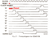
Hi all I want to know when a CLOCK pulse giving to the 4017, the outputs begin to switch ON one by one. After reaching to 10th output its again comes to the first output.

My question is let say now the 5th output is turned ON. Now I’m removing the clock pulse. What will happen to the 5th output? Is it still remains ON?

At this stage I will reset the 4017 & not giving a clock pulse. Will the first output turned ON or OFF?

Thanks a lot.
 
The datasheet shows the minimum duration for each clock pulse depending on supply voltage. If the clock pulse is too short then the counter will not count it.
When it is reset then the first output is high.
 
Gayan Soyza said:
LED's are OFF
No.
The datasheet shows that one output is always high. When it is reset then the "0" output goes high.
 

Attachments

  • CD4017.PNG
    CD4017.PNG
    10.4 KB · Views: 786
I tried after removing the clock pulse & inserted a switch.

If there is clock pulse it will go HIGH after reset. But if there is no pulse it will stay OFF after reset. some how I must give a try to get it confirm.
 
Gayan Soyza said:
I tried after removing the clock pulse & inserted a switch.
The clock pin must be made high or low. If you disconnect the clock input then use a resistor to ground to make the clock input low.

If there is clock pulse it will go HIGH after reset. But if there is no pulse it will stay OFF after reset.
Which output stays OFF after reset? The "0" output is the first output and it goes high for reset. The "1" output is the second output and it goes low for reset, then it goes high for the next clock pulse.
 
audioguru said:
The clock pin must be made high or low. If you disconnect the clock input then use a resistor to ground to make the clock input low.

Same manner I did bringing the clock in to LOW.

Which output stays OFF after reset? .

The 0 output.(all outputs OFF)

To check When power up without a clock (clock ground) the outputs all OFF condition in my IC.
 
Last edited:
The CD4017 has outputs from 0 to 9. But the internal counters are binary that count from 0 to 15. So at power-up, it randomly starts at a count which might be from 10 to 15 so no outputs are high. A few clock pulses will reset it.
 
audioguru said:
The CD4017 has outputs from 0 to 9. But the internal counters are binary that count from 0 to 15. So at power-up, it randomly starts at a count which might be from 10 to 15 so no outputs are high. A few clock pulses will reset it.

Hi audioguru,

This simple explanation should amplify why we recommend to all Newbie budding designers, not to expect a device to power up
in a sane state and that they should always ensure their logic is actively initialised.

Regards

OT, I thought this link maybe of interest to you

**broken link removed**
 
Hi Eric,
The CD4017 counter/decoder and CD4060 counter/timer are very old.
Newer Cmos counter ICs automatically reset when power is applied. An example is the CD4541.
 
audioguru said:
The CD4017 has outputs from 0 to 9. But the internal counters are binary that count from 0 to 15. So at power-up, it randomly starts at a count which might be from 10 to 15 so no outputs are high. A few clock pulses will reset it.
The details are slightly different. The CD4017 is a Johnson counter, and has 5 flip-flops, so it can power up in any state in the range 0 to 31. If it comes up in an illegal state, there is an internal gate which will force it into one of the legal states after a few clock cycles, after which it will continue in the Johnson counter sequence:

00000
10000
11000
11100
11110
11111
01111
00111
00011
00001
00000
etc.
 

Attachments

  • cd4017 sch.PNG
    cd4017 sch.PNG
    20.1 KB · Views: 740
Thanks for the replies guys.

When the 5th output is now ON.Now when I give a clock LOW (remove CLOCK) and reset the IC it will show blank (all OFF state).
 
Suraj143 said:
When the 5th output is now ON.Now when I give a clock LOW (remove CLOCK) and reset the IC it will show blank (all OFF state).
No, one output is on. When it is reset then the "0" output at pin3 should be high.
 
Status
Not open for further replies.

Latest threads

Back
Top