Continue to Site

Welcome to our site!

Electro Tech is an online community (with over 170,000 members) who enjoy talking about and building electronic circuits, projects and gadgets. To participate you need to register. Registration is free. Click here to register now.

  • Welcome to our site! Electro Tech is an online community (with over 170,000 members) who enjoy talking about and building electronic circuits, projects and gadgets. To participate you need to register. Registration is free. Click here to register now.

4017 Decade Counter

Status
Not open for further replies.

shaneshane1

New Member
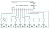
Hi, when ever i connect power to the 4017 the outputs are random and dont start at output 0 (Pin 3)

i was just wondering if there is a way to get it to start at pin 3 when ever i connect power, i am using a 555 1 second square wave for the clock, with a cap on pin 8, so it has nothing to do with spikes on the 555.

So does anyone have any ideas on how i can fix this problem
 

Attachments

  • 4017.PNG
    4017.PNG
    16 KB · Views: 4,290
Last edited:
4017 counter

you will have a random counter if you don't reset the chip. Take pin15 high to reset and low to count. After a reset count starts at zero.

Your schematic doesn't have a power on reset either.
 
Last edited:
matk95 definetly, when its running all the LED'S light up in order, its just that it starts random when connecting power?
 
hi,
Look at this option.
 
Last edited:
it works becuse it has a 10k pull up risitor becuse cmos logic chip pins flote high so you have to pull them down and the capacitor is to smoth the powere so there are no spikes ect
 
shaneshane1 said:
thanks, that works, But how though???

A power ON, the 0.01uF cap is not charged, it starts to charge via the 10K, the charge current/voltage drop across the 10K, makes the RESET line +V for a short time, until the cap is partially charged.
As the cap is fully charged the current falls to zero and so the 10K connects the RESET to 0v, removing the +V.

Do you follow that?:)
 
ericgibbs said:
A power ON, the 0.01uF cap is not charged, it starts to charge via the 10K, the charge current/voltage drop across the 10K, makes the RESET line +V for a short time, until the cap is partially charged.
As the cap is fully charged the current falls to zero and so the 10K connects the RESET to 0v, removing the +V.

Do you follow that?:)

Yes, But i just tried connecting pin 15 (Reset) to +V and it also works 100%, but the tutorials say for normal operation connect pin 15 to ground, well that gives a random start, to me thats not normal operation?
 
shaneshane1 said:
Yes, But i just tried connecting pin 15 (Reset) to +V and it also works 100%, but the tutorials say for normal operation connect pin 15 to ground, well that gives a random start, to me thats not normal operation?

hi,
The cap/res pair gives an automatic power on RESET to the 4017, avoiding the need to physically touch the RESET to +V.

For 'normal' operation the RESET pin is effectively connected to ground thru the 10K.
 
shaneshane1 said:
sorry no it doesnt work, it just holds the output high, i just didnt test it long inuf to realise that.

hi Shane,
For background information, if you ever use an ic that requires a low [0v] signal to RESET it, just swop the res/cap over..OK

Resistor to +V, cap to 0V and the junction of the res/cap to the /RESET pin.;)


EDIT:

if you wanted to add a 'manual' RESET switch to you 4017, connect it across the cap. [momentary normally open sw]
 
Last edited:
ericgibbs said:
hi Shane,
For background information, if you ever use an ic that requires a low [0v] signal to RESET it, just swop the res/cap over..OK

Resistor to +V, cap to 0V and the junction of the res/cap to the /RESET pin.;)


EDIT:

if you wanted to add a 'manual' RESET switch to you 4017, connect it across the cap. [momentary normally open sw]


thanks for the info, i really appreciate it eric, sometimes i have trouble working out RC times,from what i can understand from what you have posted is that the 10K pulldown resistor keeps the reset pin (15) low, and when power is connected to the 4017 the cap charges for a short time holding pin 15 high (for the reset) and the 10K drains the cap and pin 15 goes low???
 
hi
>>> thanks for the info, i really appreciate it eric, sometimes i have trouble working out RC times,from what i can understand from what you have posted is that the 10K pulldown resistor keeps the reset pin (15) low, and when power is connected to the 4017 the cap charges for a short time holding pin 15 high (for the reset) and the 10K drains the cap and pin 15 goes low???
hi,
All correct, except the last bit,,, the current thru the resistor, charging the cap gradually falls to zero, so the voltage across the resistor gradually falls from about +V to 0v. As the 4017 is a CMOS device, the 10k effectively connects the RESET pin to 0V....:)

EDIT:
added a sketch [ excuse the graphs, they are supposed to be exponential.:eek:
 
Last edited:
Make the time constant longer. If your power supply has a slow risetime when you turn it on, you won't get a good logic high at the reset pin with 10k and 10nF (that's only a 100usec time constant). Try 100k and 100nF, or even 1uF.
 
Here's a sim that shows what I'm talking about. I set the 9V power supply to rise at 1 volt per millisecond, just as an example. You may be using a different voltage, and your turn on slew rate may be different, but the principle still holds. I show the reset voltage for 3 different time constants.
 

Attachments

  • power on reset sch.PNG
    power on reset sch.PNG
    9.1 KB · Views: 411
  • power on reset waves.PNG
    power on reset waves.PNG
    21.5 KB · Views: 340
I've used 1M with 100pf and never had any problems but I suppose it depends on how long it takes for your power supply to come on.
 
Hero999 said:
I've used 1M with 100pf and never had any problems but I suppose it depends on how long it takes for your power supply to come on.
If you are using a switch between the power supply and the circuit, or if you have a battery, then it will work fine. If you are turning on AC power to a power supply, it could require a longer time constant.
 
ericgibbs said:
hi
>>> thanks for the info, i really appreciate it eric, sometimes i have trouble working out RC times,from what i can understand from what you have posted is that the 10K pulldown resistor keeps the reset pin (15) low, and when power is connected to the 4017 the cap charges for a short time holding pin 15 high (for the reset) and the 10K drains the cap and pin 15 goes low???
hi,
All correct, except the last bit,,, the current thru the resistor, charging the cap gradually falls to zero, so the voltage across the resistor gradually falls from about +V to 0v. As the 4017 is a CMOS device, the 10k effectively connects the RESET pin to 0V....:)

Confused a little :confused: , so does this mean that the capacitors negative pin is +V until the cap is charged?
 
shaneshane1 said:
Confused a little :confused: , so does this mean that the capacitors negative pin is +V until the cap is charged?

Yes, immediately when power is ON.

Just think of an uncharged capacitor as a short-circuited component which doesn't have no voltage across its two terminals.
 
Status
Not open for further replies.

Latest threads

New Articles From Microcontroller Tips

Back
Top