Hello Folks,
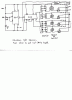
I am using this IC with a 555 timer to trigger a series of solid state relays.
I tested my circuit on a seperate breadboard and everything worked fine: i.e. the solenoids fired at preset sequence. However, when I assembled everthing on the final board for installing into the control, I nothing works properly. The problem is, upon powerup, all the solenoids fire at once and now nothing fires in sequence. Do I have to tie the unused pins of the 4017 to ground?
")