Continue to Site

Welcome to our site!

Electro Tech is an online community (with over 170,000 members) who enjoy talking about and building electronic circuits, projects and gadgets. To participate you need to register. Registration is free. Click here to register now.

  • Welcome to our site! Electro Tech is an online community (with over 170,000 members) who enjoy talking about and building electronic circuits, projects and gadgets. To participate you need to register. Registration is free. Click here to register now.

4017 as a variable resistor??

Status
Not open for further replies.
It's a counter it should count and output it if you use 1 2 and 4 you should get 3 values that only come on 1 at a time I may of draw it wrong but. you can change the 3 values
with 3 transistors and a counter the capacitors go before the transistors and are npn not pnp
 
Last edited:
here is my revised circuit

I just need to insert cap values
 

Attachments

  • Capture3-29-2009-4.21.46 PM.jpg
    Capture3-29-2009-4.21.46 PM.jpg
    165.2 KB · Views: 196
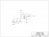
In the previous circuit, pin 7 of a 555 connects to a transistor inside the chip that only takes pin 7 to ground. It does not source any current.
Secondly, how are you discharging the capacitors in the circuit?
What is the circuit supposed to do?

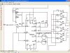
In the last circuit posted, could you make it any more complex?
How about adding a microcontroller and switch-mode power supply and a detecting circuit to detect when a LED fails.

You wonder why the Chinese and Taiwanese have taken over the electronics market.
 
Last edited:
I made something like what you want years ago it used a counter to change the tone of a 555 timer.
 
Now that is some funny stuff colin.
 
You wonder why the Chinese and Taiwanese have taken over the electronics market.
They have not taken over the market.
They sell cheap junk that does not work or does not last more than one month.
If people want to buy cheap junk then they will have many problems with it. Quality products cost a little more but work well and last forever.
 
would love to do a pic

but don't even know where to begin.
I have a Junebug on order and mplab downloaded.
I am trying.
you lost me about pin 7 sourcing??
maybe you got confused as I have a 556 with the 555 pins in (#)
circuit works in multisim but then in the real world it might not.
I got the idea from Forest Mims engineers notebook where he used caps with momentary. push buttons to select caps.
weather it will really work??
am contemplating the wailing siren but leaning towards keeping to my original plan of two separate speakers sweeping from 2-6khz back and forth.
have yet to see any deer alarm that does this. most just use ultrasonic sound.
I want to really ANNOY the deer. Hopefully won't come back.
To test I plan on setting out some grain with alarm near by. See how long the grain stays put. hopefully none gets eaten.
When the city council is asked by the citizens if there is a way the city can control the deer, the deer must be a real problem.
were not talking about a few deer were talking upwards of an estimated 100 hungry deer eating every garden in sight.
 
Pin 7 of a 555 is the collector of an NPN transistor. When the transistor is turned on when pin 6 is high enough then it usually discharges the timing capacitor through a series resistor. Pin 7 needs a resistor to the positive supply to "source" current to charge the timing capacitor.

You don't need two amplifiers driving two speakers. A single amplifier and speaker can play an entire orchestra so only two sounds are very easy for it to play.
I think he wants stereo, on the hope that it will be more annoying to the deer.
 
It works I didn't draw the whole thing out you have most of it worked out from what I have read. And Colins if your so good post some thing you did not some thing you saved from the net I at least. Draw my own circuit. Not some one else I thought there where real people on here. Maybe your radio or TV has a tuning capacitor you no the the variable kind. Mine has no moving part HOW DID THEY DO THAT. like i showed you. it's in it's simple form.
 
It works I didn't draw the whole thing out you have most of it worked out from what I have read. And Colins if your so good post some thing you did not some thing you saved from the net I at least. Draw my own circuit. Not some one else I thought there where real people on here. Maybe your radio or TV has a tuning capacitor you no the the variable kind. Mine has no moving part HOW DID THEY DO THAT. like i showed you. it's in it's simple form.
I can make your circuit sorta work, but the NPN switch is much more effective. If you think it is good, post a complete schematic with all the parts necessary to make it work.
 
I was really thinking more like this. Now i didn't work out any values but it should work seeing you can bring one of the capacitors in to play at a time which should change the output.
 

Attachments

  • 555tone.PNG
    555tone.PNG
    7.1 KB · Views: 176
Last edited:
I was really thinking more like this. Now i didn't work out any values but it should work seeing you can bring one of the capacitors in to play at a time which should change the output.
Well, s..t!! That's the same thing that MrDEB is doing. You sent a bunch of us down the garden path with your PNPs connected to the discharge pin.
 
Last edited:
Well I should of looked at his last circuit the one i started with the pnp was a monostable it would have to be triggered and change the capacitor value
 
pin 7 (discharge) has power

maybe because I forgot to change the 4.5v to 9volts? but the discharge pins (556) have 9v+ connected to them.
see R4 & R5
I realize that the gizmo will work using one sound output device but then I wouldn't get an annoying cycling effect (maybe I am just hoping that 2 is better than 1??
think about it 2 frequencies out of phase of each other (one going up while the other is going down) might be really annoying.
It would defiantly be different. unlike any thing on the market??
and R3 ?? it was in the circuit I am using as a reference.
 

Attachments

  • Capture3-29-2009-9.14.05 PM.jpg
    Capture3-29-2009-9.14.05 PM.jpg
    170.6 KB · Views: 173
It works I didn't draw the whole thing out you have most of it worked out from what I have read. And Colins if your so good post some thing you did not some thing you saved from the net I at least. Draw my own circuit. Not some one else I thought there where real people on here. Maybe your radio or TV has a tuning capacitor you no the the variable kind. Mine has no moving part HOW DID THEY DO THAT. like i showed you. it's in it's simple form.
We are real people and see that your schematics do not work.
Most modern tuners are tuned with voltage on a varicap diode, not manually with an old fashioned moving variable capacitor.
 
That's funny I wasn't taking about you and I think I told him that he could use a varicap diode to change his capacitor value and you said it wouldn't work and you missed the part
Mine has no moving part HOW DID THEY DO THAT
I think your great
audioguru you have some of the best post on here. You no I added to Colins reputation he posted something good. Then it like where i post he pops up with some thing dum to say about it with out showing how he would do it. Now to me real people try to help people and not be a kid about it. I know that you know more then me. But that don't mean what I said will not work It just may not work Like you would do it.
 
And some thing to think about I had some one to say you can't hook a red led to 120AC with a 10 kohm resistor it will burn it up the led still works like it did when I first plugged it into the wall outlet now it shouldn't but it still working I think that's what bread boards are for to try and see with out have to solder and throw away
 
Status
Not open for further replies.

Latest threads

New Articles From Microcontroller Tips

Back
Top