Continue to Site

Welcome to our site!

Electro Tech is an online community (with over 170,000 members) who enjoy talking about and building electronic circuits, projects and gadgets. To participate you need to register. Registration is free. Click here to register now.

  • Welcome to our site! Electro Tech is an online community (with over 170,000 members) who enjoy talking about and building electronic circuits, projects and gadgets. To participate you need to register. Registration is free. Click here to register now.

4017 as a variable resistor??

Status
Not open for further replies.
your right again Audioguru

I caculated withthe resistor values reversed.
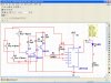
the pulse position modulator you mentioned (need to look at data sheet) and varying the voltage on pin 5 sounds like a VCO using a 555 (have a circuit somewhere?
I thought about that, its still simmering in the gray matter
as far as a "siren" perhaps , depends on what one calls a siren.
but yes I want the sound to have 2 seperate speakers or ? and have them crisscross
#1 = 2khz, 3khz,4khz,5khz,6khz then back again 5,4,3,2,
#2 to start at 6khz and go down to 2khz then back again
Hoping that it will really bother the deer and scare them away for good.
 
Have you considered a barking dog sound? Or maybe mountain lion urine? Of course, that would also probably keep people away.:p
 
Maybe you can make some form of a scarecrow. Instead of the usual pointy hat he can sport a bright red hunters cap and the obnoxious orange vest. Oh, and a Dick Cheney mask :)
 
if I made an Obama scarecrow

then the deer would be attracted, seeing how Obama wants to have more gun laws or ban them --lol
I tried adding a 10k resistor to grd from pin 5 then a 1k 100ohm and a 500 ohm resistors controlled by transistors but the frequency goes low but won't go up proportionaly.
goes down to 3khz (accoprding to Multisim) then 3400 then 4khz.
I need to do some research as to how much voltage on pin 5 to equate to desired frequency
 
revised 555 circuit for multi frequencies

by subbing different capacitors I can achieve the desired frequencies.
just need to figure out custom caps by putting in parallel or is it series??
.001uf = 6.8khz
.0013uf=5khz
.0017uf=4khz
.002uf=3khz
.005uf=1371khz
I wonder just how well Multisim works?? as far as accuracy.
I tried the caps on the collector and it doesn't work.
 

Attachments

  • Capture3-28-2009-6.55.14 PM.jpg
    Capture3-28-2009-6.55.14 PM.jpg
    252.3 KB · Views: 247
You could try a variable capacitor is the varactor
One well known implementation of the variable capacitor is the varactor, typically realized as a p-n junction diode. A varactor is a nonlinear device that provides a capacitance that varies responsive to an applied control voltage. The capacitance of a varactor, when within its operating parameters, decreases as a voltage applied to the device increases. A diode-type of device is often used as a varactor. Varactor diodes are operated in a reverse-bias operating mode. When the diode is reverse-biased, the capacitance
Varicap - Wikipedia, the free encyclopedia
 
Last edited:
This is the third and last time I am going to suggest this:

Do you want a wailing siren circuit that goes from 2kHz to 7kHz and back again?

This is the normal way to cover all the frequencies to annoy an animal.


I get more attention from my 17 year old students.
 
by subbing different capacitors I can achieve the desired frequencies......
I tried the caps on the collector and it doesn't work.
The capacitors are on the collectors. That is the only way that transistors will sub the capacitors.

The base-emitter of each transistor will instantly burn out without current-limiting resistors.
 
Last edited:
sorry colin55 I missed posting your answer

yes I want it to vary from 2-6khz back and forth but two separate sirens
while one goes up the other goes down
a varicap that is controlled by say a 4017??
yes I forgot to add some base resistors. I had resistors on the emitters yesterday, just didn't (I forgot)get put in.
how big is the next question seeing how a capacitor is the load??
 
Varicaps are usually in the picofarad range. I doubt this would be large enough for your purpose.
 
I say things like this is why they use pic that way you can make a IC the way you want it.
It looks like you could use your 4017 to turn on say 6 transistors with 6 capacitors and you
would have 6 tones. Then you have 2-4-6kz with one haft of your 556 and 6-4-2.
 
I have a simple circuit that produces a wailing siren sound and drives a piezo transducer to about 100dB.
 
will it scan the frequencies??

post the circuit and I could breadboard it and try it out
this project could use a pic but I myself am just getting started in using pic.
got a junebug on its way and mplab downloaded. just need to decipher how to use them both.
 
thanks I will give it a go

how are all them roos doing these days?
I understand they are pretty good eating.
have you built this circuit??
 
We have roos running down the main street of most of our villages, but we haven't learnt how to catch them yet.
 
Mr DEB have you tried it like this
 

Attachments

  • 555.PNG
    555.PNG
    6.1 KB · Views: 167
you show pnp transistors

wouldn't all the caps be in the circuit then instead of individually except for one?
unless I am mistaken the 4017 outputs go high sequentially??
 
Status
Not open for further replies.

Latest threads

New Articles From Microcontroller Tips

Back
Top