Continue to Site

Welcome to our site!

Electro Tech is an online community (with over 170,000 members) who enjoy talking about and building electronic circuits, projects and gadgets. To participate you need to register. Registration is free. Click here to register now.

  • Welcome to our site! Electro Tech is an online community (with over 170,000 members) who enjoy talking about and building electronic circuits, projects and gadgets. To participate you need to register. Registration is free. Click here to register now.

4017 as a variable resistor??

Status
Not open for further replies.

MrDEB

Well-Known Member
I had 4066 ic's w/ resistors connected but came up with this idea.
not even sure if its cosure??
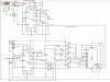
the 4017 supplies the voltage to the 556 disc pin (pin 6 on the 555) which the 556 is connected as an astable timer.
the 4017 adds resistors so the output frequencies change.
I want to cycle from 2khz, 3khz, 4khz on one output and 6khz, 5khz, 4khz on the second output.
but will the 4017 supply enought for the 556 to operate
normally the disc pin is connected to vcc via a resistor which determnes the frequency.
any input as to feasability??
 

Attachments

  • Capture3-14-093-21-2009-5.36.12 PM.jpg
    Capture3-14-093-21-2009-5.36.12 PM.jpg
    152 KB · Views: 568
You may have a problem with the 4017 because the output has two levels, either high or low.
I have used 4000 series analog switches to connect different resistors and different capacitors to the 555 timer to change frequencies. It worked with the analog switches as when the particular gate is not selected it is an open circuit. I once buit a circuit that had 2ea 4067 analog switches so I could select 32 different frequencies.
I hope this helps
 
Last edited:
You are changing the value of the resistor that affects the duty-cycle a lot and affects the frequency a little.
But the other resistor needs both of its ends free.
 
would love to do this with a pic

but being a beginner and this is expermental (see DEER CHASER post.
I am trying to cut down the parts count.
If I could get someone to program some chips then I would be in bussiness on this circuit.
I myself have been looking at different programming boards and language but hav't decided. Pocket book gets in the way as well.
If I could get someone to program some chips, I would be willing to pay for them either cash or trade (I do custom woodworking like portraits, furniture etc.)
I am hoping to be able to sell the Deer Chaser and have my scout troop assemble them so the troop can make some money.
 
What you are saying is incorrect:

You are changing the value of the resistor that affects the duty-cycle a lot and affects the frequency a little.

**broken link removed**

The output of the 4017 can be connected to pin 7 via a resistor but since the output can both sink and source, you will have to gate them to prevent the other outputs from interfering with the result.
 
Last edited:
Everything looks like a nail after a while =) Then again, after a while, everything IS a nail.
 
It would be very simple with a PIC but first you have to get a programmer (either JDM or PICkit-2 with extn socket <snip>) and a PIC12F629 and then everyone here will help you program it. You will also need a prototyping board with 5 pins for In circuit Programming.

But we really don't know what you want to do.
 
Last edited by a moderator:
What you are saying is incorrect
No.
I am correct. I am making a variable frequrency 555 oscillator.
Your circuit changes the duty-cycle of the pulses.


**broken link removed**
 

Attachments

  • 555 variable frequency oscillator.PNG
    555 variable frequency oscillator.PNG
    4.9 KB · Views: 356
Everyone here will be able to help but me and you colin.
I'll be pushing AVR's, you'll be referencing other peoples code and circuits and pushing your website.
 
Not really. The circuit I submitted: PULSE GENERATOR, has a constant-width LOW but the HIGH changes in length and this creates the different frequency.
 
Last edited:
You can push AVR's all you like. If you can help someone who knows absolutley nothing about programming and wants to produce a project for $10.00 to deliver a particular application, then show me the website and instruction-set that enables him to do so.
I get people started, who know absolutley nothing about programming. Pushing my website does not bring in any money. My main kits are train kits.
I chose PIC 8 years ago because it had the biggest following and support on the web.

I am not against any microprocessor but when I asked for 300,000 ATiny12's they said they were going out of production.
I had to get MCV08A - a PIC chip made expressly for the Chinese market.
 
It would be very simple with a PIC but first you have to get a programmer (either JDM or PICkit-2 with extn socket as described on talkingelectronics.com site) and a PIC12F629 and then everyone here will help you program it. You will also need a prototyping board with 5 pins for In circuit Programming.
Yup that will break the bank. $15 for a programmer from sparkfun which should work fine if an old PC can be found(better to spend a bit more and get a PICkit2 or clone). You can run the ICSP cable to a breadboard to do the programming. But there is that bit about not knowing how to program.

We are a bit on the gullable side here. From time to time we help people, even write code or layout PCBs.

A uC is not as far fetched as you might think.

3v0 :)
 
Last edited:
colin55, my first AVR project was programmed on free samples that were included with a 27 dollar serial based ISP programmer because Id idn't want to make my own, you can interface any AVR that support ISP programming via a serial port with any machien that lets you run the software (win98) I don't generally provide the links for stuff like that because personally I think the first thing anyone interested in micro controllers should do is research things for THEMSELF, it's how I learned everything I know and chose the chips I have, and I have no trouble. Hand feed people schematics and code and you learn jack.
 
That's wonderful. You are a highly intelligent electronics person who knows what he is doing.
Many newcomers are struggling with electronics in the first place and they don't have the capability of go out and buy a kit and do it themselves. That's why they are looking at sites like this.
And when I contacted Parallax about the number of projects produced by reader’s they said about 100, even though 1,200,000 Stamps had been sold.
Even when hand-feeding, it's extremely difficult.
 
I didn't mean to raise some dust

If you boys can't play together nicely then you both can go to your room without dinner--LOL
I plan on buying a programming board, looking at the JuneBug as well as the PICKIT2.
BUT I need to assemble a prototype so I can test it out on some deer.
The deer are staring to appear in town as we type.
My plan is build 5 units using ic's as in my schematic. need to reduce the parts count etc. if possiable
have 5 PIR moduls from SURE Electronics on there way.
Get 5 in operation while designing units using a PIC.
Problem is learning how to program a PIC.
Time is a concern RIGHT NOW. not 3 months from now.
PIR module? Is this to warn people that there is a deer in their yard, or is it to scare away deer?
 
Last edited:
straight lines/revisions

YES this device is to scare deer away. The PIR is used to detect the deer
Instead of using the 4066 I figure why not use some 2n2222 transistors.
the 4017 outputs need resistors (I come up with 4500 for 2ma to base. the 4017 outputs up to 5ma.Just forgot to insert.
Maybe one resistor as I have seen here somewhere??
 

Attachments

  • Capture3-14-093-22-2009-12.35.06 PM.jpg
    Capture3-14-093-22-2009-12.35.06 PM.jpg
    140.8 KB · Views: 316
a VCO /556/4017

revised the DEER CHASER circuit so the timming resistors stay put as per audioguru suggestion.
Well how about a VCO where the resistor combos R9 or R11 + R12 = voltage divider (R8 or R10 + R13) to change the frequency of the 556 output.
The resistor combos need to be calculated (need to find out what values for desired frequency)
changed the piezo units to speakers.
I want a two tone sound= 1st tone goes from 2khz to 3khz to 4khz.
2nd tone from 6khz to 5khz to 4khz
tones then recycle until 10 seconds has passed.
 

Attachments

  • Capture3-26-2009-4.46.04 AM.jpg
    Capture3-26-2009-4.46.04 AM.jpg
    174.9 KB · Views: 260
The 556 will melt if it tries to drive 8 ohm speakers. You need a stereo power amplifier. Also the 556 would try to put DC in the speakers which is bad.
Why two channels?

Have you calculated the actual sound level at the distance of the deer? The deer might need to wear the speakers on their ears to be scared away.
 
Last edited:
Status
Not open for further replies.

Latest threads

New Articles From Microcontroller Tips

Back
Top