Continue to Site

Welcome to our site!

Electro Tech is an online community (with over 170,000 members) who enjoy talking about and building electronic circuits, projects and gadgets. To participate you need to register. Registration is free. Click here to register now.

  • Welcome to our site! Electro Tech is an online community (with over 170,000 members) who enjoy talking about and building electronic circuits, projects and gadgets. To participate you need to register. Registration is free. Click here to register now.

3vdc low voltage circuit

Status
Not open for further replies.

b_reagle

New Member
Hello,
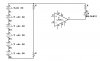
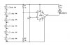
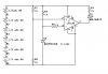
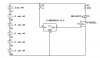
I need to sense the voltage of batteries(6 AA's in series), and to know when they are at 3vdc or so (maybe 2vdc) to drive a circuit that will flash a LED at about 1 Hz. Maybe with 555 timer and comparator. I am not sure where to start, or the most effecient way. Thanks for the help.
 
That's a cool part. Available a Digi-key too :)
 
Last edited:
2VDC, that's just 0.333V per cell, alkalines will probably leak and rechargables will die if discharged to that voltage.

If you go for the old fashioned approach an LM311 comparator bandgap referance, potential divider and flashing LED is the way to go.
 
2VDC, that's just 0.333V per cell, alkalines will probably leak and rechargables will die if discharged to that voltage.

If you go for the old fashioned approach an LM311 comparator bandgap referance, potential divider and flashing LED is the way to go.

Number 1: Would 3 vdc be better or should it be higher?

Number 2: Could you explain that a little better(differtent)

Thanks
 
Where do I go from here?
 

Attachments

  • lowvoltage.jpg
    lowvoltage.jpg
    34.1 KB · Views: 207
Take a look here. Explains comparators.

**broken link removed**
 
I don't know what to do from here. The sites help a little, but not much for someone who doesn't know what they are doing. lol This is all I have now. Can someone steer me in the right direction?
 

Attachments

  • lowvoltage.jpg
    lowvoltage.jpg
    39.3 KB · Views: 243
Ok, here is the thing. You want to detect when your batts drop to say 3V. You are also using batt voltage to power your 311. Problem is that the 311 needs +5v to operate, so when you batt dies so will your circuit. The other problem is that your also using your batt as your vref. When the batt dies so does Vref. The nice thing about the part Kchriste suggested is that it has built in Vref so the drop in batt voltage will not cause a problem. And the part is only 3 pins.
I think the LM139 operates down to 2vdc.
 
Last edited:
Would this work? Maybe it draws too much power.
 

Attachments

  • lowvoltage.jpg
    lowvoltage.jpg
    44.6 KB · Views: 300
Number 1: Would 3 vdc be better or should it be higher?

Number 2: Could you explain that a little better(differtent)

Thanks

I would normally say about 0.8V per cell giving a total voltage of 4.8V for six cells. Rechargeables are more sensitive, ideally you need a coulomb counter but more practically speaking cutting the load at between 0.9V and 1V will do.
 
Last edited:
Looks like your getting the idea, but you still have a few problems with the circuit. I recommend the following changes:

  • Your LED is in backwards
  • Move Vref to + pin of amp
  • Vsense to - pin
  • For Vsense just use a pot instead of divider, then you can adjust your set point.
 
One more thing. Your schematic symbol for the 139 is all wrong, Pin assignments. I assume you know that however.
 
Looks like your getting the idea, but you still have a few problems with the circuit. I recommend the following changes:

  • Your LED is in backwards
  • Move Vref to + pin of amp
  • Vsense to - pin
  • For Vsense just use a pot instead of divider, then you can adjust your set point.
If he does the things that I have highlighted in red, the LED will be on until the voltage drops below Vref. I don't think that's what he wants. Of course, he really wants a flasher anyway, so an LED on the comparator output ain't gonna work anyway.
 
When voltage drops to 4.8 (as suggested), then blinking LED will blink. I was informed that the batteries would start at 6vdc and then normally operate at 4 vdc. I have not done my research to comfirm this. I am not sure if LM139 is the way I want to go. There is alot of unused gates.(room, power, and size are issues) Am I getting closer with this...?
 

Attachments

  • lowvoltage.jpg
    lowvoltage.jpg
    55.4 KB · Views: 146
Whoops, I mean like this:
 

Attachments

  • lowvoltage.jpg
    lowvoltage.jpg
    54.6 KB · Views: 145
If he does the things that I have highlighted in red, the LED will be on until the voltage drops below Vref. I don't think that's what he wants. Of course, he really wants a flasher anyway, so an LED on the comparator output ain't gonna work anyway.

Oops, your right. Now that is just embarrassing :eek:
 
What about like this?
 

Attachments

  • lowvoltage2.jpg
    lowvoltage2.jpg
    35 KB · Views: 202
After my last blunder, I am somewhat afraid to give out advice, but just one comment.
For U1, from the part number you listed, the device has an open drain output which means it needs a pull up and is an active low out.
 
Status
Not open for further replies.

Latest threads

New Articles From Microcontroller Tips

Back
Top