Nightowl171
New Member
I'm a real noob to electronics (although I did have an electronics hobby kit back in 1972) as my paths of employment took me away from the hobby, but I'm retired now, so I've got some time on my hands - and you know what they say about idle hands..!
Anyway, I'm happy to provide more details if necessary, but essentially I have a machine control board that normally runs via a (UK) mains-powered 24V 350W PSU, and the machine has the facility to record certain information to a 'resume' file, if that power should fail. However, the power 'drain' for my machine is too quick so the file isn't written.
The control board can also run with a 5V (USB) power supply (but not to do any work, just when configuring it) and I was hoping to use this as a way of keeping the board powered long enough to save the file, but both shouldn't provide power at the same time, so I thought of using a pair of relays and a microcontroller, to switch from one supply to the other, if the 24V fails - and it sounded so simple.
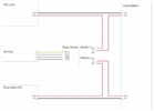
Here's a sketch of my thoughts (it's not really a circuit diagram) and I'm hoping the principle is sound, but I'm not quite sure how to get the microcontroller to recognise the failure of the 24V supply, as it can only tolerate 3.3-5VDC. I'm thinking perhaps an optocoupler?
Any suggestions would be appreciated, but (I think) I'm fairly happy about the code for the microcontroller.
Thank you.


