marktait12
New Member
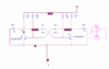
Hi, I'm trying to simulate a 38kHz signal to use an IR transmitter signal on Pspice with no luck. I have tried to use a 555 timer but now trying to resort back to just implementing the multivibrator. Would anyone be able to help determine what my issues are?
I have attached my circuit and below is the error message I get from PSpice.
**** 03/14/21 23:01:15 ******* PSpice 17.4.0 (Nov 2018) ******* ID# 0 ********
** Profile: "SCHEMATIC1-test" [ C:\Users\Mark\Desktop\EE318pro2\circuit2-pspicefiles\schematic1\test.sim ]
**** CIRCUIT DESCRIPTION
******************************************************************************
** Creating circuit file "test.cir"
** WARNING: THIS AUTOMATICALLY GENERATED FILE MAY BE OVERWRITTEN BY SUBSEQUENT SIMULATIONS
*Libraries:
* Profile Libraries :
* Local Libraries :
* From [PSPICE NETLIST] section of C:\SPB_DATA\cdssetup\OrCAD_PSpice\17.4.0\PSpice.ini file:
.lib "nom.lib"
*Analysis directives:
.TRAN 0 200u 0
.OPTIONS ADVCONV
.PROBE64 V(alias(*)) I(alias(*)) W(alias(*)) D(alias(*)) NOISE(alias(*))
.INC "..\SCHEMATIC1.net"
**** INCLUDING SCHEMATIC1.net ****
* source CIRCUIT2
C_C8 0 N11131 100p TC=0,0
R_R13 0 N11279 1k TC=0,0
R_R11 N11171 VCC 1k TC=0,0
X_U4 0 N11131 N11279 VCC N11269 N11131 N11171 VCC 555C
R_R12 N11131 N11171 191k TC=0,0
C_C7 0 N11269 0.01u TC=0,0
V_V3 VCC 0 5v
R_R15 N14329 VCC 1k TC=0,0
R_R16 N14369 VCC 1.9k TC=0,0
R_R17 N14385 VCC 1.9k TC=0,0
R_R18 N14317 VCC 1k TC=0,0
C_C9 N14385 N14329 0.01u TC=0,0
C_C10 N14317 N14369 0.01u TC=0,0
Q_Q1 N14317 N14385 N14487 Q2PC4081Q/PLP
Q_Q2 N14329 N14369 N14487 Q2PC4081Q/PLP
R_R19 N14487 N14317 1k TC=0,0
R_R20 N14329 N14487 1k TC=0,0
R_R22 N16054 VCC 91k TC=0,0
R_R23 N16058 VCC 91k TC=0,0
R_R24 N16062 VCC 2.2k TC=0,0
Q_Q4 N16062 N16058 0 Q2PC4081Q/PLP
R_R25 N16050 0 1k TC=0,0
Q_Q3 N16050 N16054 0 Q2PC4081Q/PLP
R_R21 N16050 VCC 2.2k TC=0,0
C_C12 N16062 N16054 220n TC=0,0
R_R26 0 N16062 1k TC=0,0
C_C11 N16058 N16050 220n TC=0,0
R_R27 0 N14487 1G TC=0,0
**** RESUMING test.cir ****
.END
**** 03/14/21 23:01:15 ******* PSpice 17.4.0 (Nov 2018) ******* ID# 0 ********
** Profile: "SCHEMATIC1-test" [ C:\Users\Mark\Desktop\EE318pro2\circuit2-pspicefiles\schematic1\test.sim ]
**** Diode MODEL PARAMETERS
******************************************************************************
X_U4.DIODE
IS 10.000000E-15
RS .01
**** 03/14/21 23:01:15 ******* PSpice 17.4.0 (Nov 2018) ******* ID# 0 ********
** Profile: "SCHEMATIC1-test" [ C:\Users\Mark\Desktop\EE318pro2\circuit2-pspicefiles\schematic1\test.sim ]
**** BJT MODEL PARAMETERS
******************************************************************************
Q2PC4081Q/PLP
NPN
LEVEL 1
IS 15.330000E-15
BF 178.7
NF 1.002
VAF 69.7
IKF .1216
ISE 793.200000E-18
NE 1.436
BR 8.628
NR 1.004
VAR 44.7
IKR .1121
ISC 83.050000E-15
NC 1.207
ISS 0
RB 1
RBM 1
IRB 1.000000E-06
RE .361
RC 1.382
CJE 14.570000E-12
VJE .65
MJE .3393
CJC 3.511000E-12
VJC .4485
MJC .3646
XCJC .6193
CJS 0
VJS .75
MJS .333
FC .9256
TF 527.500000E-12
XTF 96.78
VTF 2.012
ITF .4793
TR 0
KF 0
AF 1
CN 2.42
D .87
**** 03/14/21 23:01:15 ******* PSpice 17.4.0 (Nov 2018) ******* ID# 0 ********
** Profile: "SCHEMATIC1-test" [ C:\Users\Mark\Desktop\EE318pro2\circuit2-pspicefiles\schematic1\test.sim ]
**** Junction FET MODEL PARAMETERS
******************************************************************************
X_U4.JNEMOD
NJF
VTO -2.5
BETA 5.120000E-06
**** 03/14/21 23:01:15 ******* PSpice 17.4.0 (Nov 2018) ******* ID# 0 ********
** Profile: "SCHEMATIC1-test" [ C:\Users\Mark\Desktop\EE318pro2\circuit2-pspicefiles\schematic1\test.sim ]
**** MOSFET MODEL PARAMETERS
******************************************************************************
X_U4.PCHAN555 X_U4.NCHAN555
PMOS NMOS
LEVEL 1 1
L 100.000000E-06 100.000000E-06
W 100.000000E-06 100.000000E-06
VTO -.2 .2
KP 20.000000E-06 20.000000E-06
GAMMA 0 0
PHI .6 .6
LAMBDA 0 0
IS 10.000000E-15 10.000000E-15
JS 0 0
PB .8 .8
PBSW .8 .8
CJ 0 0
CJSW 0 0
CGSO 1.000000E-12 1.000000E-12
CGDO 1.000000E-12 1.000000E-12
CGBO 1.000000E-12 1.000000E-12
TOX 0 0
XJ 0 0
UCRIT 10.000000E+03 10.000000E+03
DIOMOD 1 1
VFB 0 0
LETA 0 0
WETA 0 0
U0 0 0
TEMP 0 0
VDD 5 5
XPART 0 0
X_U4.PCHAN555_OUT
PMOS
LEVEL 1
L 100.000000E-06
W 100.000000E-06
VTO -.2
KP 20.000000E-06
GAMMA 0
PHI .6
LAMBDA 0
IS 10.000000E-15
JS 0
PB .8
PBSW .8
CBD 200.000000E-12
CJ 0
CJSW 0
CGSO 1.000000E-12
CGDO 1.000000E-12
CGBO 1.000000E-12
TOX 0
XJ 0
UCRIT 10.000000E+03
DIOMOD 1
VFB 0
LETA 0
WETA 0
U0 0
TEMP 0
VDD 5
XPART 0
Starting pseudo-transient algorithm.
ERROR -- Convergence problem in transient bias point calculation
Last node voltages tried were:
NODE VOLTAGE NODE VOLTAGE NODE VOLTAGE NODE VOLTAGE
( VCC) 5.0000 (N11131) 3.2166 (N11171) 4.9907 (N11269) 3.3333
(N11279) 4.7109 (N14317) 5.0000 (N14329) 5.0000 (N14369) 5.0000
(N14385) 5.0000 (N14487) 5.0000 (N16050) 1.5625 (N16054) .0328
(N16058) .6699 (N16062) .0763 (X_U4.1) 431.7E-12 (X_U4.2) 1.6667
(X_U4.3)-15.50E+03 (X_U4.4) 4.2000 (X_U4.5) -.6665 (X_U4.6)-1167.0000
(X_U4.7) 4.2000 (X_U4.8) -.5995 (X_U4.9) 880.4E-06 (X_U4.10) 5.0000
(X_U4.11) .2891 (X_U4.12) 5.0000
(X_U4.13) 431.7E-12 (X_U4.14) 1.486E-09
(X_U4.15) 5.0000 (X_U4.16) 5.0000
(X_U4.17) 89.17E-12 (X_U4.18) 416.0E-12
(X_U4.19) 207.8E-12 (X_U4.20) 5.0000
(X_U4.21) .2005 (X_U4.22) 4.7957
(X_U4.23) .1336 (X_U4.24) 5.0000
(X_U4.25) 104.5E-12 (X_U4.VDD) 5.0000
These voltages failed to converge:
V(N11131) = 5.000V \ 3.217V
V(N11279) = 3.182V \ 4.711V
V(N11171) = 5.000V \ 4.991V
V(N16054) = 5.000V \ 32.77mV
V(N16062) = 75.35mV \ 76.26mV
V(X_U4.3) = -33.33KV \ -15.50KV
V(X_U4.23) = 103.77mV \ 133.55mV
V(X_U4.5) = -696.23mV \ -666.45mV
V(X_U4.6) = 16.67KV \ -1.167KV
V(X_U4.21) = 595.56mV \ 200.45mV
V(X_U4.8) = -204.44mV \ -599.55mV
V(X_U4.9) = 280.47mV \ 880.38uV
V(X_U4.11) = 1.818V \ 289.12mV
V(X_U4.20) = 4.822V \ 5.000V
V(X_U4.22) = 4.757V \ 4.796V
These supply currents failed to converge:
I(X_U4.E_EMIR) = -4.586mA \ -4.751mA
I(X_U4.E_EVAL) = 0A \ -10.34pA
I(X_U4.E_U6_E1CMP) = 3.333mA \ 1.550mA
I(X_U4.E_U7_E1CMP) = -1.667mA \ 116.72uA
I(V_V3) = -3.918mA \ -3.981mA
I(X_U4.V_U6_V2) = -3.333mA \ -1.550mA
I(X_U4.V_U7_V2) = 1.667mA \ -116.74uA
These devices failed to converge:
X_U4.D_U6_D1CLMP X_U4.D_U7_D1CLMP X_U4.M_U2_U1_M4 X_U4.M_U2_U1_M6
X_U4.M_U2_U1_M8 X_U4.M_U2_U1_M1 X_U4.M_U2_U1_M2 X_U4.M_U2_U1_M5
X_U4.M_U2_U2_M6 X_U4.M_U2_U2_M1 X_U4.M_U2_U2_M2 X_U4.M_U2_U2_M7
X_U4.M_U2_U3_M1 X_U4.M_U2_U3_M3 X_U4.M_U2_U4_M3 X_U4.M_U2_U4_M4
X_U4.M_U2_U5_M2 X_U4.M_U2_U5_M3 X_U4.M_U2_U5_M4 X_U4.M_U2_U6_M3
X_U4.M_U2_U7_M2 Q_Q3
ERROR(ORPSIM-15659): Discontinuing simulation due to convergence problem
**** Interrupt ****
Any help appreciated.
Regards,
Mark