Continue to Site

Welcome to our site!

Electro Tech is an online community (with over 170,000 members) who enjoy talking about and building electronic circuits, projects and gadgets. To participate you need to register. Registration is free. Click here to register now.

  • Welcome to our site! Electro Tech is an online community (with over 170,000 members) who enjoy talking about and building electronic circuits, projects and gadgets. To participate you need to register. Registration is free. Click here to register now.

30f article project (note thread)

Status
Not open for further replies.

large_ghostman

Well-Known Member
Most Helpful Member
hi, i want to have a bash at doing a article :eek: and i want to have a play around with 16 bit pic's (30f4013 or 30f4011) and as i havnt really seen much on here about stuf being done with 30f pics so i thought i would document my experiments with the 30f and if i get far enough to a article on it.
so this thread is kind of my note book/experiments page/log, and from this i hope to get an article together!
i will also post pics.

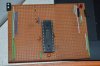
first job on my list is getting a simple experiment board together, first one will be strip board untill i have a better idea wich way i am going. i was going to use a bread board but so far i havnt used a crystal before i have always used internal oscillator, so i thought parasitic's might mess me about if i use a BB. so strip board first then maybe a simple 30f PCB DEV board.
second on list will be getting fuses set up and a crystal set up and working, i will probably go with a 8Mghz to start with.
next a simple flash a LED:meh:
then ADC 12 bit
after that i am not sure but at some point i would like a go with CAN
anyway hopefully tomorrow i will start and get some pics together

LG
i forgot to add that were i can i will try and not use the libs but if i get stuck i will use a lib to get it working and then try again with not using the lib if that makes sense!
 
Excellent lg, look forward to reading it.
Never used 16 bit pics, however I have many times run pics on breadboard at 20 mc's without any caps or resistors, just the xtal and its allways been fine.
 
not got very far yet as i have mainly been getting used to the datasheet, but reading the timer section has given me an idea for making a modified metal detector i saw on the web using mikro c and a coil on the main crystal input. instead i will use a couple of the timers to try and do the same thing
 
I breadboarded the one that uses a 12f675, it used a standard inductor as a pick up, it worked but not really well.
Pulse induction is the way to go for metal detectors if you want real performance.
 
ok first update,
so far just done a very basic strip board, i will add to it as i do stuff but for now is just basic so i can see if i can get it up and running

i tried to upload a pic but dosnt seem to have worked! how do you upload a pic from hard drive? i tried upload file but no luck
 
ok will try again but so far no luck with pic unless..
 

Attachments

  • DSC_4729.JPG
    DSC_4729.JPG
    4.3 MB · Views: 230
That seems to work. You can also try copy and paste (ctrl+C and ctrl + V). John
 
third attempt! yay. anyway back to the ramblings as this is after all just a notebook type thread for later. the pc i do mplab stuff on is a win7 64 bit machine, i dont use the laptop (mums) for coding. anyway plugged in ICD3 and powered up the board, i was informed that it had to download software for the chip type (i really really really hate HATE this ) it did it ok and then reported the chip was id xxxxxxxxx and it was expecting zzzzzzzz, now normally i get this message with major problems or board shorts or some other foof up, so i unplugged ICD3 and plugged PK3 it also wanted to download a new firmware for the chip type (microchip you utter numpty's for this! it's really crap stop doing it), the PK3 hung!!! now there is a thread on here i did that explains how i got the ICD3 but in a nutshell win7 64 bit has the ability to brick PK3's when downloading new AP's etc. so in a panic i disconnected everything and fired up vmware wich is running 32bit winxp opened mplab in that and downloaded the new AP etc. apparently the not so many problems with ICD and win7 64bit because MC said that it has it's own driver where as the PK3 uses a window usb driver. anyway pk3 alive and well with the new AP but people shouldn't have to do this!!!
for now dads PK3 has 18f firmware on it and i will keep mine with 30f firmware for now as well as the ICD3.
so back into win7 and mplab and try again to connect to board! still no luck still getting wrong device ID, so checked device i had selected in the project and discover that i had chosen 30f3014 and not 30f4013! in my rush to try out i had messed up the chip selection! really noob error and down to me rushing as normal! more attention to detail needed. ICD and PK3 connect to board now! way hay!! and thats as far as i have got, for now i will use the config settings via mplab rather than code them in software, main reason is i am not sure of the format for the 30f and unlike c18 c30 dosnt have the handy config settings help file for each chip (MC sort that out it was real handy!!)
 
thanks John!
BTW stuff in italics is just bits for me to remember or stand out as normally in my lab book
right, already noticed some big differences with these 30f 16 bitters, the ports are numbered differently for a start, on 18f chips you gets ports like RB0--RB7 on the 30f4013 port B is RB0--RB12!
then you get odd ports like port D that goes RD0--RD3 RD8--RD9 and strange stuff like that!
so datasheet reading a big must and porting 18f code over to 30f might be a bit of a challenge, other big thing i found in the datasheet peripherals seem to take presidence over port I/O so in 18f you turn a peripheral on when you want to use it (generally) on the 30f it looks like if you want normal I/O on a port you have to make sure the peripheral it share the port with is off! this i can see catching me out a few times if i dont pay close attention to the book!
one other small thing ihave noticed is on 18f datasheets it has arrows on the pin diagrams showing if the pin is bidirectional IO or open drain etc, the 30f datasheet dosnt has this wich is a shame as it made a good shortcut. anyway i am off to try and do a simple LED blink :rolleyes:, if thats a success i will start to delve deeper, also once i get a led to blink i will alter the board so it can take a crystal in a socket, that gives me the option to change crystals without constantly soldering and desoldering them.
 
well ive got the chip running, very simple program i wont bother posting code for it yet. i have also added a couple of test points to the board so i can see out output on the scope (eqv of flashing led lol). first thing ive noticed is i have set fuse in mplad config to use internal osc and all default osc settings, turning a pin on then straight off with no other code gives me a squre wave of around 234Khz. seems very slow so will delve back into the DS and see what the deal is with setting up the internal osc for say 8Mhz.
ALSO i am using the scope on the little LA that sits on the computer desk (HP LA) its a ok scope not my fave but pretty good, but first surprise is the output on the scope, i am using a really good PSU (HP) that has a very very clean output, but the square wave when the program is running looks awful! undershoot and overshoot and spikey at the top of the wave not nice and straight at all! i will try and get a pic of it to post. ANY idea's why it should be like that? i have decoup on all power pins except to the ADC module and the signal going into the cheap is clean,

edit apparently internal OSC is 7.37 Mghz, so another difference with 18f seems to be the internal OSC in 18f's seem alot more configurable for different speeds and not just limited to PLL for adjustment! also on alot of 18f chips i use you can set to use internal OSC but have one the external clk pins as IO and the other as CLK out so it's easy to probe the CLK out pin x4 to get an idea what your chip is running at but so far i cant find a similar setting for this chip, also the datasheet seems a bit vague and keeps referring you back to the family sheet for more details! annoying,
but still we are getting there! will post simple code and drawing soon just so you know exactly where i am at
 
Last edited:
might be time to have a bash with external crystal!
 
been reading more and trying to cross ref with the family datasheet wich the chip datasheet keeps telling me to see that for details of x y z. documentation on 30f seems way more confusing than 8 bitters.
anyway school is on holiday for 2 weeks now so i get some time to delve deeper next week.
hopefully next few days i will have something more interesting post and maybe start to make progress!
i am starting to see why people dont do more with 16 bit chips! and there dosnt seem to be many tutorials on the net for the 30f4013 chip.
if i can get over the initial hurdles then i have some good stuff i want to look into :D
 
thanks EM, this is just a notes thread really but i will make a proper article/tutorial from it :D
 
just a minor update, in the datasheet as mentioned before and in a couple of books on 16bit pics they all pretty much give the impression that a peripheral takes precedence over a IO port, and indeed in more than one example code in the book (ok i admit it's a 24f chip in the book) they use simple turn led on/off on the ADC pins as an example. what is meant to happen is you set the TRIS and run the program but the led dosnt light, then it goes on to explain that is because you have to first give the port over to digital control. So anyway this is what i was expecting to happen, except it didnt! it seems the ADC port on the 30f4013 has the first 13 bits set as digital on start up, the register for changeing digital IO to analogue on port B is the ADPCFG register.
ADC set up looks a bit more complex than normal 8 bit chips so will get to that after i have messed with the timers.
 
ok quick update, i have gone back to looking at the oscillator again, mainly i am trying to see if i can monitor CLK output on the OSC2 pin so i can verify the frequency the internal osc is running at. I have gone round and round in circles with this all day, seems i need to look at the FPR reg <4:0> now it appears this is all tied up with the configs (fuses) but when you look at the configs menu in mplab its all a bit sparse and dosnt give a option for internal and OSC2 pin, so probally going to have to set it in software wich i wanted to avoid for now as this led to problem 2!! could not find the 30f4013.H file!!!!! turns out it's actually in the folder called support! (seems dopey to me), so if anyone else is stuck on finding it then now you know! so next job trawl through H file and find out config syntax etc, i hate this bit as i am not great reading theese files and working out what they mean, but i will give it a good go and report back! on a positive note havnt got far but feels like ive learned alot and getting better with datasheets! slowly finding my way round :D also i havnt had to ask for help yet!! YAY, i am sure i will need it soon though lol
 
quick up[date found the config stuff in the H file near the end so some reading up and then i might switch to setting config in software
 
hmmm not found what i was hoping for! i am still convinced is there must be a way to do it but cant find the info i am looking for! maybe a trawl through google will give some code that i can take a look at the config settings but i am doubtful. i might ask MC and see if there is a way to set FPR reg for OSC2 as I/O when you use internal Oscillator, its only a small thing i know but the info should be more easy to find than it is. seems there are so many setting's for OSC yet the FPR is hardly mentioned!
soon as that is done i can start the real stuff! the next bit will be timers so its kind of important that i ind out exactly what speed we are running at or it makes it hard to do any calculations.
the timers (5!) look pretty good with loads of features so again start basic and work up! also will try and get code and schematics and screen shots posted today. a couple of things i want to try pretty early on are uart, reason being there are two on this chip so might be good to do a serial backpack using a 8bitter for a LCD. this i will do on PCB board as trying to get a serial socket mounted on sripboard is horrible! and that should at least give anyone following this thread something worth reading :D.
still too early to start actually doing a draft of the article but i am taking plenty notes and pics and screen shots! who knows might even be the first reasonable tutorial on the 30f4013 chip!!

edit

forgot to mention i have been monitoring the power consumption while doing all this and will post details later but it wasnt what i was expecting! the chip uses more mA just sitting doing nothing than it does when actually running a simple led on/off routine! so i might deviate and investigate that later.
 
dont want to try it yet incase i brick the chip again but i may have solved the OSC problem!! i have posted in other section to see if i am right, if so i will update with solution
 
Status
Not open for further replies.

Latest threads

New Articles From Microcontroller Tips

Back
Top