Continue to Site

Welcome to our site!

Electro Tech is an online community (with over 170,000 members) who enjoy talking about and building electronic circuits, projects and gadgets. To participate you need to register. Registration is free. Click here to register now.

  • Welcome to our site! Electro Tech is an online community (with over 170,000 members) who enjoy talking about and building electronic circuits, projects and gadgets. To participate you need to register. Registration is free. Click here to register now.

3 transistors' Chinese audio amplifer with Huge distortion

Status
Not open for further replies.

Willen

Well-Known Member
I found a professional computer audio amplifier made by China. When I opened it was amazingly simple. So I listened the output audio performance carefully and heard distorted audio. It was not playing clean audio like an audio amplifier chip plays. However its simplicity and loud audio is impressive.

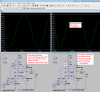
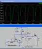
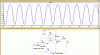
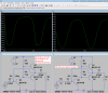
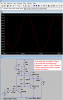
When I made a simulation, I saw huge distortion. Here I have attached a simulation file (.asc) for LTspice.

In the next post (#2) I have uploaded screen shoot of the simulation. So please observe the files and suggest me to reduce the huge distortion. I changed some components but not being able to decrease distortion.
Regards
 

Attachments

  • Transistors' distorted audio amplifier SIM file.asc
    1.7 KB · Views: 213
Last edited:
Here is a screen shoot of the simulation. Huge distorted waveform fo the audio amplifier. (I posted this 2nd post too because I cannot upload multiple files from my java cell phone browser.)
 

Attachments

  • Transistors' distorted audio amplifier.GIF
    Transistors' distorted audio amplifier.GIF
    18 KB · Views: 221
I guess that the design objectives were:

1 Make it as cheaply as possible
2 Have some sound come out of it
3 Make it as cheaply as possible.

It looks like the cost of components and board stuffing labour for that thing worked out cheaper that say an LM386 which would (probably) have less distortion.

JimB
 
At 1 kHz, the .33 uF capacitor has an impedance of 483 ohms. Tis is too small givn the size of the feedback resistor, 180 K. The circuit has too much gain. To correct this, insert a 300 resistor in series with the .33 uF input capacitor to reduce the gain, or connect the input to the wiper of a pot to reduce the input. Either of those methods should eliminate the clipping.

Other than that, there is not much you can do, The output transistors are driven by an asymmetrical impedance, with the transistor pulling down and 680 ohms pulling up. Increasing R2 from 100 to 200 will decrease the crossover distortion but increase the static current through the output stage.

ak
 
Last edited:
Hi Willen,
All it needs is an extra resistor 10R and change in value from 100R to 150R and its almost acceptable.
E
 

Attachments

  • AAesp03.gif
    AAesp03.gif
    43.3 KB · Views: 210
  • SIM file(1).asc
    1.7 KB · Views: 192
I fixed it:
1) The sim has a signal source with ZERO ohms output impedance that shorts AC negative feedback from R3. I added R5 as 1k then later changed it to 3k ohms to reduce the gain and distortion.
2) I changed R2 to two diodes that match the base-emitter voltages of the output transistors.
3) I added bootstrapping with C3 and R6 to increase the gain and maximum output level.
 

Attachments

  • removing distiortion-1.png
    removing distiortion-1.png
    51 KB · Views: 196
  • removing distortion-2.png
    removing distortion-2.png
    31.9 KB · Views: 208
I guess that the design objectives were:
1 Make it as cheaply as possible
2 Have some sound come out of it
3 Make it as cheaply as possible.

agu,
I would go with JimB on this 'design'.
Adding numerous extra components would not meet the original design specification.
 
IDK if those few extra components make a bottom line difference, I suppose the 'cheaper is better' approach supports that.
I must support ag here in that a bit of effort in quality can make a product more desirable and hence command a better price.
That said, I suffer from a bad case of feature creep whenever I am designing something so....grain of salt etc.
 
The design dictum I usually try to follow is "Make it as simple as possible, but no simpler" (as paraphrased from Albert).
I think AG's circuit modification follows that principle quite well.
I think the original circuit doesn't.
 
That said, I suffer from a bad case of feature creep whenever I am designing something so....grain of salt etc.

Hi Mosiac,
I agree that feature creep can be a problem, is unfortunate some 'design engineers' lose sight of the product budget and the selling price.

It is the Christmas tree syndrome, they have to keep added bits to the tree and finally by placing a Fairy on top they make the tree top heavy and it becomes prone to 'crashing'.;)

E
 
The trouble is you are "pulling down" the push-pull output with a capability of a few ohms (via the transistor) but pulling up via 680 ohms.
This gives an uneven output, even though the first transistor is producing a fairly good quality signal.
There is nothing better you can do with just 3 transistors.
 
ag could u explain that bootstrapping technique pls?

Edit..nvm..
I checked it out..
https://www.learnabout-electronics.org/Amplifiers/amplifiers43.php

It does indicate that it adds distortion though

You're not checking the correct type of bootstrapping, it considerably increases power output and considerably reduces distortion (by greatly increasing base drive capability of positive going signals). A similar technique is to replace the top resistor (680 ohm) with a constant current source.

I'd also like to see some emitter resistors on the outputs, to prevent thermal runaway - and on that line I wouldn't use two diodes, I'd use a fourth transistor as a Vbe multiplier.
 
It does indicate that it adds distortion though
My circuit uses bootstrapping to increase the output impedance of the voltage amplifier transistor and allows its output to swing above the supply voltage with fairly good linearity. Good linearity is low distortion.

The bootstrapping capacitor C3 causes a constant current in R1 so that the impedance of R1 is very high increasing the gain and allows the base of Q1 to swing above the supply voltage.
Look at the voltage amplifying transistor Q3 without bootstrapping then with the bootstrapping.

Colin, adding bootstrapping makes the simple 3 transistors amplifier work VERY WELL, when it also has negative feedback..
 

Attachments

  • bootstrapping demo.png
    bootstrapping demo.png
    51.6 KB · Views: 183
ag could u explain that bootstrapping technique pls?
Irt does indicate that it adds distortion though

Actually, it says it *might* add distortion, without saying how much and what kind. In fact it is more likely to add a small amount of noise. It is a very common technique for increasing the input impedance.

Thanks for the link. It is an excellent resource.

ak
 
agu,
I would go with JimB on this 'design'.
Adding numerous extra components would not meet the original design specification.

Agree. In terms of modification Q (increase in performance divided by increase in complexity), I think eric wins with post #5. After my post I was thinking about a recent exchange with Wally about degeneration. I was writing it up when eric beat me to it.

ak
 
In terms of modification Q
An interesting term of phrase there AK.
I like it.

JimB
 
I hate cheap simple amplifier circuits that sound awful.
I improved the circuit's performance immensely by adding 3 inexpensive parts and changing a resistor for a diode.
 
Status
Not open for further replies.

Latest threads

New Articles From Microcontroller Tips

Back
Top