Continue to Site

Welcome to our site!

Electro Tech is an online community (with over 170,000 members) who enjoy talking about and building electronic circuits, projects and gadgets. To participate you need to register. Registration is free. Click here to register now.

  • Welcome to our site! Electro Tech is an online community (with over 170,000 members) who enjoy talking about and building electronic circuits, projects and gadgets. To participate you need to register. Registration is free. Click here to register now.

3 MHz Sawtooth Generator Needed with Discrete Parts Only!

Status
Not open for further replies.

Teketron357

New Member
Hi everyone,

Merry Christmas and Happy New Year to all the forum!!!


I am in need of a design for a 3 MHz Sawtooth Generator with discrete parts only.

Details:

Frequency = 3 MHz
Amplitude = Vpp 12V (if variable preferred, but not needed)

I have looked at the following thread:

https://www.electro-tech-online.com/threads/sawtooth-generator-circuit.100724/

But, the frequency only goes for 0.5 MHz and they are using ICs and some discrete parts (but not 100% discrete and not 3 MHz).

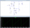
I have tested the following circuit:

LinearRamp2.PNG


With some changes (Changing R2 and the Capacitor C1) to the above circuit, I have achieved a 1 MHz Sawtooth signal, but a little crooked (not highly linear). The problem with this is that Transistor Q2 gets really HOT.


Also, I have tested the following Sawtooth generator from the link:

http://www.all-electric.com/schematic/eticircuits/stable-high-linearity-saw-tooth-generator.htm

But, it does not work at all and the Uni-junction formed by Q1 and Q2 (Q1 burns like crazy) .


I would really like to get some ideas from you guys to achieve the 3 MHz sawtooth generator with discrete parts. :)

Thank you,
-Steve.
 
What's the purpose of the high frequency sawtooth?

Why no ICs?
 
What's the purpose of the high frequency sawtooth?

Why no ICs?


Hi, yes I ask myself the same question. Since we are studying oscillators and discrete design (transistors only, no ICs), we are to build a 3 MHz sawtooth.
I have seen some ICs such us the LM555 being used to generate sawtooth signal, but it will not go over 600 KHz or something like that (that is the limit of that IC).

In the end, any IC in the market is built out of a network of transistors. But, I would like to achieve it at the 3 MHz level. I have already reached the 1 MHz level as mentioned in the post, but one of the transistors is getting really HOT.

Simulations: Huh, in the simulation everything can look beautiful, but the real TRUTH will be revealed once physically tried. Most likely it will turn out that things are NOT what shown on simulations.

If anyone reading this thread has any ideas for a 3 MHz Sawtooth oscillator built with TRANSISTORS only, please give the enlightenment.

Regards,
-Steve.
 
Huh, in the simulation everything can look beautiful, but the real TRUTH will be revealed once physically tried.
Very true. I ran a higher frequency version of the sim you showed in post #1, but with small resistances inserted in series with Q3 emitter and/or D1. Resistance even as low as 0.4Ω could kill the oscillation, so I guess a real-world implementation might be problematic :(.
 
Hello there,


When you generate the ramping portion of the sawtooth the capacitor charges slowly as the voltage builds up. This can be done with a constant current source.
The problem is, in order to reset the sawtooth (the portion where the wave comes down very fast) the capacitor has to be discharged. Doing this often means a lot of dissipation in any transistor that is drawing the energy out of the cap, and in order to have a very fast fall it has to dissipate some power.
So the first question that comes up is, just how fast do you have to reset the sawtooth? Can you get away with 1/10 the total period, or 1/5 the period, or does it have to be more like 1/100 of the period?
That's the first criterion that we have to know in order to design this thing, and it's very important to specify this parameter.

If it turns out that it doesnt have to be too fast then all we have to do is add some resistance to slow down the cap discharge.

If it turns out that it has to be extremely fast however, then the only way might be to use a dual phase sawtooth where there are two capacitors being charged. One is being charged while the other is being discharged, and the one being charged is the one that is selected to be directed to the output (via more transistors or analog switch). This way the cap can be discharged more slowly through a reasonably sized resistance. So the waveform across each cap would look like a triangle, but 180 degrees out of phase with each other, and the output would be a sawtooth with required ramp time and very fast drop time.
Alternately we might be able to generate a triangle and invert and level shift the period between 180 and 360 degrees. That way the cap would charge and discharge slowly but we'd still get a sawtooth output.

So first you have to specify what the drop time has to be (maximum) so we can decide how to proceed.
 
Last edited:
Thank you MrAl for taking the time to look into this. Yes, you are right the transistor discharging the capacitor is the one that takes all the beating. Now, since the 3 MHz sawtooth is the goal: That would give a period of about 333 nano seconds <--- I would say that a good VHF transistor can handle this (those are the ones that I have used). I would say that with 1/25 to 1/30 the period would be OK for the sawtooth drop. Although the 1/100 would be the ideal for the sawtooth drop (but I am guessing this would be way too much and would make the design more complicated than needed, so dual sawtooth may be out of question).

Thank you,
-Steve.
 
Last edited:
Hello again,

Ok, so what circuit ideas led you to the current design?
And can you post your asc file here too?
 
Hello again,

Ok, so what circuit ideas led you to the current design?
And can you post your asc file here too?


OK, the circuit was obtained from the following link: http://www.vk2zay.net/article/196

I have tested it physically and not simulate it myself. I will upload the pics from the oscilloscope tomorrow.

Question: Since the transistor that discharges the the capacitor must act fast and have some good power dissipation, would the 2N3866A be a good choice.
Data sheet here: https://www.electro-tech-online.com/custompdfs/2012/12/2N3866A.pdf

From data sheet, it has 800 MHz fT and 1 Watt power dissipation.
 
Here is a simulation of my version.
 

Attachments

  • Sawtooth gen 3MHz.PNG
    Sawtooth gen 3MHz.PNG
    43.5 KB · Views: 1,658
  • 3MHz sawtooth gen.asc
    2.1 KB · Views: 343
Here is a simulation of my version.

WOW! Hi Roff, thank you for your input. I see you are using a constant current source to charge the capacitor (how many mA is it?). Then, I see the fast discharge switch you created with 2N5771 and the BAT54 (Schottky Diode).

Question 1: I have seen the BAT54 in many circuit diagrams, is there a Through Hole version of this Schottky diode?

Question 2: Are you using LTspice for this simulation run?

Thank you,
-Steve.
 
Last edited:
back in the 70's i saw a version that used a jfet as the constant current source, and another jfet to discharge the capacitor. the discharge fet needed to be driven by a pulse generator, but the output was very linear.

roff's version has the advantage of free running, rather than requiring an external pulse source.
 
Last edited:
The current is about 4.1mA, The 2N5771 and 2N2369 are designed to be very high speed saturating switches, with low storage time (recovery from saturation). The BAT54 is a Baker clamp, keeping the 2N2369 out of saturation for even higher speed switching. I don't know if there is a through-hole version of it.

I am using LTspice. I included the file needed for simulation. If you want to run it, you might need a model for the BAT54. If you can't find one, I can post it here.
 
Last edited:
back in the 70's i saw a version that used a jfet as the constant current source, and another jfet to discharge the capacitor. the discharge fet needed to be driven by a pulse generator, but the output was very linear.

roff's version has the advantage of free running, rather than requiring an external pulse source.

I see. Do you recall or have scans of the version that you mentioned with the JFET? <--- Just out of curiosity on this. Yes, the version that Roff has provided appears good.
 
The current is about 4.1mA, The 2N5771 and 2N2369 are designed to be very high speed saturating switches, with low storage time (recovery from saturation). The BAT54 is a Baker clamp, keeping the 2N2369 out of saturation for even higher speed switching. I don't know if there is a through-hole version of it.

I am using LTspice. I included the file needed for simulation. If you want to run it, you might need a model for the BAT54. If you can't find one, I can post it here.

Thank you. It appears that BAT54 is manufactured in SMD only (no suitable through hole version appears to exist).
It would really help to have the BAT54 model for LTspice. I am new to LTspice.


Regards,
-Steve.
 
Thank you. It appears that BAT54 is manufactured in SMD only (no suitable through hole version appears to exist).
It would really help to have the BAT54 model for LTspice. I am new to LTspice.


Regards,
-Steve.
LTspice comes with the BAT54 model already in the library.
 
LTspice comes with the BAT54 model already in the library.

Ooops! Thanks (new to LTspice here). LTspice seems easy to use once you have the model set-up. Yes, the the BAT54 is in the library. I am running the simulation and playing around with it to get use to LTspice.

Many Thanks, I will update once I physically build it. I am ordering the the 2N5771, 2N2369 and BAT54 since I do not have them in my component bin.

By the way, for the 2N5771, is it the only PNP high speed saturated switching in existence? The 2N5771 is a little hard to find or really expensive to buy compare to other 2N series transistors.
 
Last edited:
If you can't get a 2N5771 try a 2N3906. Sim shows it works nearly as well.
If you want to sim a jpfet used as a constant-current sorce in Roff's circuit to charge the cap C1, replace Q3 and Q4 with a single 2N5460 or similar, with its gate connected to the +V rail, source to R4, drain to C1. Make R4 330Ω. A BAT46WJ can substitute for a BAT54.
 

Attachments

  • TriangleGen2.asc
    1.8 KB · Views: 246
If you can't get a 2N5771 try a 2N3906. Sim shows it works nearly as well.
If you want to sim a jpfet used as a constant-current sorce in Roff's circuit to charge the cap C1, replace Q3 and Q4 with a single 2N5460 or similar, with its gate connected to the +V rail, source to R4, drain to C1. Make R4 330Ω. A BAT46WJ can substitute for a BAT54.
The JFET current source will almost certainly need to have a pot to set the current, because the transistor's parameters vary wildly from one part to the next. Of course, the BJT current source will probably also need a pot, also to compensate for component tolerances.
In your simulation, I noticed that the voltage on the base of the PNP never reaches full value, due to the RC time constant of the node. I don't think this is a good idea. One reason is that the peak voltage will be dependent on frequency. I would make the Thevenin resistance of R3 and R4 low enough to avoid this situation.
I also noticed that your current source is starting to saturate near the peak of the sawtooth. This accounts for the flattening as the ramp nears the peak.
The biggest problem is that, with the supply slowly ramping up from 0V to 15V (I used a 1ms ramp-up), your oscillator does not start. Lowering the resistance of r3-R4 will solve this problem.
 
Points taken. So perhaps R3 = 1k, R4 = 3k3?
 
Status
Not open for further replies.

Latest threads

New Articles From Microcontroller Tips

Back
Top