Raiway Pete
New Member
Reply to Angie1199
Hi Angie,
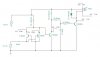
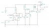
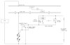
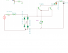
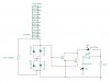
I did not see a jumper across the output of the bridge rectifier. Maybe I'm old and my eyes are dim but I just saw two diodes "pushing" up against each other and another two "pulling", the current flow being zero. I'll take a closer look.
I am assuming that you have parked cars on a block without an engine.
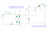
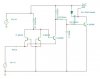
The circuit should work OK, but the maximum value of resistance should be around 1.5K in the load circuit. Higher than that and the there won't be enough current available to "light" the photocoupler's LEDs. You have to perform a balancing act between the number of cars per block and the max current your DCC power supply can hande. If you want to detect a single car then to make sure that at the detector fires cleanly you should put a 1.5K resistor across all four of its axles. If three fall out then you still have enough OOmph from the last conducting one to fire the detector. When all four axles are conducting then the total resistance per car will be 375 ohms.
Now when you have ten cars like this on your layout the total resistance will drop to 37.5 ohms. Make it twenty and your 2 amp booster is supplying half its max load. AND you havent moved an engine yet. Yikes!
Lastly the 1.4 volt drop is constant and applies to each block on your layout. the 1.4 volt drop is not accumulative. If you use this detector then all your blocks will have 14.6 volts across the track. No Problem.
Hi Angie,
I did not see a jumper across the output of the bridge rectifier. Maybe I'm old and my eyes are dim but I just saw two diodes "pushing" up against each other and another two "pulling", the current flow being zero. I'll take a closer look.
I am assuming that you have parked cars on a block without an engine.
The circuit should work OK, but the maximum value of resistance should be around 1.5K in the load circuit. Higher than that and the there won't be enough current available to "light" the photocoupler's LEDs. You have to perform a balancing act between the number of cars per block and the max current your DCC power supply can hande. If you want to detect a single car then to make sure that at the detector fires cleanly you should put a 1.5K resistor across all four of its axles. If three fall out then you still have enough OOmph from the last conducting one to fire the detector. When all four axles are conducting then the total resistance per car will be 375 ohms.
Now when you have ten cars like this on your layout the total resistance will drop to 37.5 ohms. Make it twenty and your 2 amp booster is supplying half its max load. AND you havent moved an engine yet. Yikes!
Lastly the 1.4 volt drop is constant and applies to each block on your layout. the 1.4 volt drop is not accumulative. If you use this detector then all your blocks will have 14.6 volts across the track. No Problem.
")

")