Continue to Site

Welcome to our site!

Electro Tech is an online community (with over 170,000 members) who enjoy talking about and building electronic circuits, projects and gadgets. To participate you need to register. Registration is free. Click here to register now.

  • Welcome to our site! Electro Tech is an online community (with over 170,000 members) who enjoy talking about and building electronic circuits, projects and gadgets. To participate you need to register. Registration is free. Click here to register now.

3 aspect model RR signalling help plse

Status
Not open for further replies.
A single car has to provide a resistance of 1.6 Kohms across the track because that is the very minimum current required to trigger the isolator.
If you can assume that you'll never leave fewer than n cars sitting alone on a block, and there will always be n cars, the resistance can be n*1.6k. 10k, for example, would suit a situation where all trains are >5 cars.

Situations where a train has 4 trailing cars on a block that it was just leaving would be (incorrectly) signaled as an empty block. But an approaching train would see red when it hits this block (since the next one shows occupied), and must stop at least 4 car lengths short of the end.
 
Ok, so now everyone's lost me completely, we're now saying the NMRA circuit is too heavy a circuit and probably more useful for garden railways where they use 24V and 5 to 10 amp boosters and don't have too many locos/wagons using the same booster?

So what of the original block detector I was looking at?
**broken link removed**

This says it has 1mA current sensitivity. Now, before you go off talking different resistances, please try not to forget I'm no Tesla.

I do understand the logic of comparators though but not how they work. I believe I am correct in saying that the comparator simply compares two current values, and if A doesn't equal B then block is occupied. Is this correct?
 
I'm probably on thin ice here, I sell a similar circuit already built...

Hi Artificer

Thanks for the link. Not on thin ice at all. :)

This all adds to the discussion. Trouble is I'd need to be a very wealthy person to buy any 'ready made' signalling and block detector circuit boards. This is the reason for building my own. I already have one board controlling the signals working alongside 2 other blocks on a breadboard, so I know the signalling circuit works.

I only need single direction signalling so bi directional is a little over the top for my model RR.

Now it's just a case of discussing the block detector that's going to be suitable. The detector I originally looked at does 'say' it does what I need it to do and it's been tested albeit off RR but it worked.
 
I would go with your lnk
**broken link removed**
it works on LT SPICE as well as TINA
the one from NMRA has issues that I WAS trying to figure out but my computer crashed??
Ever since I put AVG on it (removed Nortons). Been conversing w/ tech support.
getting maybe cleared up?
 
Sorry bout Ur machine. I use AVG on two laptops, my workstation and two servers. Never had a problem. Hope they get it sorted soon for you.

I'm unable to do the schematic in tina as the only optocoupler I have is the 4n33 which shows the led and an npn transistor with 3 pins, collector, base and emitter. The one I need is without the base as I'm certain the base is replaced by the led lighting.
 
if your talking about the Q1 1(4n33) all I did was use an LED.
if LED lights up your good to go.
The opticoupler has an LED in it so if LED lights up then the optocoupler should go on as well.
You need to improvise, no big deal.
 
here is screen shott

will send you file as well
I need to use AC as input voltage
 

Attachments

  • tran block detect.PNG
    tran block detect.PNG
    29.1 KB · Views: 169
I have something not right??

are the diodes in series with the track?
Block Occupancy Detector
am assuming the DCC powered track is 14vAC at 60hz?
I am just not getting the schematic of these block detectors.
something does not jive??
 
Diodes in series

MrDeb,

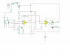
Yes that is exactly it. The four diodes are in series with the track juice. The detector takes advantage of the fact that, when conducting, a PN junction drops about 0.7 volts regardless of the current passing through it. Whether the current is 2 Amps or only 20 Ma, the voltage across the conducting PN junction will be at 0.7 volts. Each diode pair is in seies with only on half cycle. First one pair conducts and then the other. The opto-isolator is an AC device. The internal LED is actually a pair of LEDs, back to back just as the diodes.

DCC is not 60 Herz. Sorry, when we say AC that's what people think. DCC is effectively a computer communications port, running at 9600 baud. It can also pack a punch of 2 or 3 Amps. The engine decoder reads these pulses just like your serial port on your computer. It then passes the data to the on-board engine computer on the chip. The on-board computer decides if any data received is intended for itself. If not it throws it away. If the engine recognizes that it is being addressed the data bytes following the recognition byte (engine number) tell the motor, lamps and sounds what to do. There is another thing going on all the time though. The pulses can punch a high current, but as square waves, when rectified they produce almost perfect DC. That DC is used to drive the engine.

You can look at it this way. The pulses come in and a little bit of the enery is taken and decoded for the computer. The pulses are then passed to a rectifier to supply power to the engine and decoder.

Hope that helps.

Angie1199

I have been sitting at my computer and have drawn up a detectors with great sensitivity. I have stripped it of components that are essential for DC operation but not needed for DCC. The board need not be etched. Saw cuts can be used. It is about 1" by 2½" square and has ten maintainable and understandable components on it. It is designed for non-Tesla people. I want to make one first, see how it works and maybe pass it along to you. Are you game?
 
POST THE SCHEMATIC
then can simulate.
seeing how I am way off base on simming AC anyway.
do you suppose Instead of injecting AC just use dc for power to the compatator circuit?
using simple 741 op amps (really cheap etc) seeing how the twin T is using transistors anyway so I assume DC should work for simulation??
 
am assuming the DCC powered track is 14vAC at 60hz?

DCC is explained here in basics. **broken link removed**

It's basically a 16V AC squarewave which is uniform until a request is made from the loco cotroller when the wave pattern, while remaining square, changes in length to pulse a signal to a specific decoder to do something (change direction, go, stop etc.)

This is why one loco can run on the same line without interference from another loco.

From the schematic I'm assuming that the AC power is always on in the circuit but not on the track until a loco enters that block or something shorts the rails in some way and takes power from the rails. This is when the power to the detector reduces and operates the switch.

It does appear that the circuit only uses one phase of the AC wave though and can do this because of the capacitors.
 
I have been sitting at my computer and have drawn up a detectors with great sensitivity. I have stripped it of components that are essential for DC operation but not needed for DCC. The board need not be etched. Saw cuts can be used. It is about 1" by 2½" square and has ten maintainable and understandable components on it. It is designed for non-Tesla people. I want to make one first, see how it works and maybe pass it along to you. Are you game?

All solutions welcome Pete. By the time this thread closes we should have the perfect signalling and detector circuits in the world :)

As for the etching, I'm getting the hang of it now, so there's no problem there.
 
Schematics

Angie1199 and Mr Deb,

Attached is last night's work. Angie, I suggest you spray a copper clad board that's about 1¼ by 4¼ inches with some spray paint and let dry. Then score the straight lines with a ruler and sharp pointed tool or summat.

This is what the circuit will do for you. It is not high tech. I designed this for non-Tesla people who have access to an electronic surplus or mail order store. I have made the following assumtions.

You have a basic DCC system having blocked off your track and that each block has its own DCC power buss stemming from a common source (Booster).
(It is best to block off track with double gaps at each end of the track.)

DCC power is applied to all of the track blocks all of the time.

You require a method of detecting the presence of rolling stock on each block.

Your only concern at present is unidirectional signalling. (You don't need a signal at the end of each block. I guess you intent to run an express sytem requiring double track).

Here is what this circuit will do for you.

It will detect the presence of rolling stock that has a resistance from about 8 Ohms (almost a short and the limit of your 2 Amp DCC power supply) to about 50Kohms. That means the circuit will trigger at 250 MICRO Amps or there abouts. The sensitivity of the Twin-T can be adjusted by changing the value of the collector resistor (R1). The overall sensitivity will also depend on the Twin-T power resistors.That means you can use high value resistors across the car axles. I use DCC at about 1.5 volts and my detectors trigger at around 65K.

This is how the Twin-T works. T1 and T2 have their emiters and bases cross connected and in series with track power. Each transistor passes track current half the time. One for the positive half cycle and one for the negative. The base emitter current causes the common collector voltage to fall turning T3 off. This causes T3's collector voltage to rise to -18 volts (Vcc). This also causes C1 to charge relatively quickly eventually turning the relay driver T4 on and allowing current to flow through the relay coil. The capacitor is a crude but effective debouncing circuit that prevent chatter when your track gets a bit grimy. When the detector senses a clear condition (neither T1 or T2 is passing current across their PN junctions) the collectors return to -18 volts turning T3 back on, discharging C1 and eventually turning T4 back off. D1 is a safety device. When an inductive load has its current turned of it generates a very large Back EMF voltage spike which can damge a transistor. This diode shorts that spike out. The relay drops out and the signal should indicate yellow because the next block is now occupied and its relay has been activated.


You will need an extra DC power supply to run the detectors. I use and old throttle and use the AC out. I small rectifier and capacitor provide raw DC. I condition that via the use of a cheapy regulator. I get 17.9 volts. Anything up to 24 volts should work. Try a surplus store. They usually have some good ones that can be adjusted downward to around 19-20 volts.

Attached to this circuit board (on the right side of it) is a signal driver. This driver has two inputs. One from a small (off board) relay with a coil resistance from 650 Ohms up to about 2K Ohms. This input cuts off current flow to the green and yellow aspects (via D2 and D4) and supplies current to the red LED (no diode). The other input is from the relay contacts of the detector that monitors the block ahead. This input supplies current to the yellow LED (via D5) and cuts off the current to the green one (via D3). i.e. If the block ahead is occupied this input will cause this signal to turn from green to yellow IF and only if this signal is not allready red.

Practical advice and hints.

DCC uses square waves. The nice sharp corners are caused by very high frequencies which can cause the Twin-T transistors to leak a bit. This can be fixed by inserting a 0.1 micro farad capacitor (50 volts working voltage) across their emitter base cross connections. This will depend on your Dcc system. It may allready have some kind of high freqency suppression components doing the same thing.

The Twin-T circuit here uses PNP transistors (It's what I had on hand when I started) You can use NPN but all diode, LED and electrolitc capacitor connections will have to be reversed.

If you decide to build this circuit I suggest you do this in stages. Build the relay driver first and inlude R2. The relay should be activated. Test it by shorting the junction of R2 and R3 to ground (common). It should drop out.
Next install T3 and R1. Apply power and the relay should turn off. Short the junction of R1 and T3s base to ground. (Common). The relay should activate. Install T1 and apply a DC voltage via an old throttle and a current limiting resistor(from an old throttle maybe) to the input. The circuit should trigger when voltage is applied in only one direction. Install T2 and the circuit should trigger when the throttle is set to reverse.

You can now apply DCC power as shown in the diagram. Put an engine on your test track and play. As long as the engine is on the track the circuit stays triggered no matter what you do. Take the engine off the track and the circuit should drop out. Use an LED and a 1.5Kohm resistor to test the output from the relay contacts.

A word about the relay. People have a heart ache about using a relay. This is my rationale. I could use an emitter follower transistor to drive my signals but the detector might have other functions to perform; functions that include animation, automatic routing, crossing gates etc. which may use different power sources and voltages. I have used an off board relay situated next to its signal to open a 12" track section in front of it. This automatically stops a train when the track ahead is occupied and the signal indicates a red 'Halt' condition. Multi contact relays provide total isolation for such 'gee whizz' activity. The cost can be prohibitive but most surplus stores or mail order suppliers have cheapy relays for sale. My 4PDT Potter Brumfields cost about $2.50. Finally, a 5, 9, 12 or 18 volt relay will work too. You just need to put a resistor in series with it.

Good luck

Pete
 
Last edited:
'Tis late and I took a beating at a trade show today. Will post details later. The link to Signal Aspect was actually intended as an offer of etching diagrams and elementaries if they would be of use. This is my HOBBY and the design of the logic is not proprietary. The board will accomodate many different methods of detection, including Twin-T, far and away my favorite. I do have a high component count; because numerous circuits can interact with the signal systems. Thought I'd ask first before posting the rather memory hungry drawings.
 
Schematics

Pete,

First thank you for taking the time to add to this discussion but there are a few questions and concerns I have with this circuit.

Am I to assume, from the LEDs on the board, that this is a complete detection and signalling circuit? If so, where does the 'detect' end and is it possible to replace the relay with an opto isolator and remove the signalling section.

Again, assumption, the 'box' above the track is the dcc power bus, and the 'box' at left of board is alternate power source for board. If this is the case then am I correct in assuming the alternate power source connects to the dcc power bus. Is this not a problem?
 
The link to Signal Aspect was actually intended as an offer of etching diagrams and elementaries if they would be of use.

Artificer,

Please feel free to contribute. I know from the number of views that many are interested in this thread, even if not for model RR's.
 
Hi Angie,

Yes you can omit the signal controller. I just integrated everything on one board because then power is single sourced on a common bus. There is no problem. Just cut the controller off. The top and bottom foils are the power bus for both the Twin-T AND the signal controller. The only other thing connecting the two is the relay contacts. I don't think you would have a problem either by substituting an optoiolator. HOWEVER--- please understand that, depending on the type of isolator you intend to use, you might have to put a current limiting resistor in series with it. I am making assumptions here. The optoisolator mentioned (NEC2506) requires 10 Milliamps to drive it. A 1.5 to 2K ohm resistor would be about right. I suggest you try connecting an isolator of your choice with a limiting resistor in series and connect it across your power supply. i.e. Replace the relay with an opto isolator and a 2K current limiting resistor connected in series. When it gets working you can use that 555 unit to drive our signals. Remove the de-bouncing capacitor and D1. You wont need them. D1 is to protect the driver transistor from back EMF produced by the relay coil, and C1 is used as a debouncer. The 555 unit performs that function for you. Use a breadboard to experiment. When you get it working let me know :)

You have it right. The DCC power source connects to the track with the detector in series with it. The detctor(s) have their own power supply which must operate RELATIVE to something. i.e. one side of the track. Whether it is AC, square wave or pulsing DC it does not matter. There is absolutely no problem with both power supplies being connected to a common ground. Your PC has the same system. All your power supplies (and there are a few) all have some point in the PC where they are connected to a big bolted lug. That is common ground and all power supplies produce their voltages relative to this point.

Now I have a question. Do you have the signals or are you going to build your own. Are they two or three aspects. How expensive were (or are) they. I can't find decent ones for under $40. Do you have the controllers yet?

Pete
 
Status
Not open for further replies.

New Articles From Microcontroller Tips

Back
Top