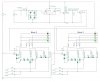
Yay!!!!!!!!!!! We have victory.

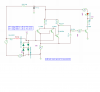
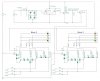
Added two signal diodes to green ground on each block.
Changed resistor R8 to 2.2K.
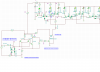
Works great with both locos and dry finger across rails.
Tried 10R resistor across rails. Worked but smoked

Have no idea what I was doing but it works. Now need to find out what power each wagons axle resistor has to be so it doesn't burn out and that's something else I don't know how to do.
")