Good God! I know the pound and dollar are in the tank but my All Electronics store still has them for much less. Or maybe it'sbecause I use 24 volt relays and the higher the volts the higher the rebate.
That's why the UK and USA are not manufacturing much anymore and we all import from the middle/far east. The Unions kept striking for more money, that put up prices for products, everyone else striked for more money to buy the more expensive products, and so on, Vicious circle till companies decided to get stuff made abroad for cheap prices and import, and now the UK has 2.5 million unemployed. And yet no one sees the logic that follows!
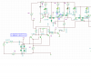
BUT before you do that hook the base of your 'detect' driver transistor directly to the Twin-T collectors. (no base resistor) Also up the Twin-T collector resistor to 3.9K. Your signal driver should work backwards (red when clear)but it should work clean. ie no dim lights. Once you got that straight I suggest you add another inverter transistor and use that to drive you signals. If that works then goodbye relays.
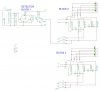
Ok, right about now a schematic would be good. I think I got it, gimme a while to sort this. I tried another circuit for detection but that didn't work at all!