Continue to Site

Welcome to our site!

Electro Tech is an online community (with over 170,000 members) who enjoy talking about and building electronic circuits, projects and gadgets. To participate you need to register. Registration is free. Click here to register now.

  • Welcome to our site! Electro Tech is an online community (with over 170,000 members) who enjoy talking about and building electronic circuits, projects and gadgets. To participate you need to register. Registration is free. Click here to register now.

3/4 hp fan motor installation HELP!

Status
Not open for further replies.

NikkiShade79

New Member
Hey Everybody!
So I'm not an electrician and I'm not really "into" electronics.... But I'm pretty mechanically inclined and I catch on quick. This project is a first for me and I don't want to mess up and have to replace this brand new motor because I didn't ask for help. So...... HELP!
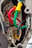
I have a single phase 3/4 hp belt drive fan motor that I'm installing. I'm going the 115 volt route and I'm just not confident in wiring a switch and plug onto this unit. I've run 10awg wire (which was recommended) ok n the motor specs for 115 volt. I'll attach pics of what I have and I'll await all the help you guys are going to give to guide me thru to successful completion

Thanks in advance!!! IMG_20190808_185717623_HDR.jpgIMG_20190808_185526104_HDR.jpgIMG_20190808_185626529_HDR.jpgIMG_20190808_182625666_HDR.jpgIMG_20190808_185244176_HDR.jpgIMG_20190808_185359503_HDR.jpg
 

Attachments

  • IMG_20190808_185526104_HDR.jpg
    IMG_20190808_185526104_HDR.jpg
    774.6 KB · Views: 106
Please I'm desperate to get this done and not look like an idiot. Any help would be appreciated. I just need to know which wires I put together when connecting the switch to the plug. When looking at the picture of the plug, the black wire is connected to the terminal on the left. I followed the schematic in the picture, with the red wire connected on the top and black wire on the bottom.
TIA
 
Ronsimpson would you say then that coming from the motor to the switch that the red wire is the hot and the black wire is neutral? Or vice versa?
 
Ronsimpson would you say then that coming from the motor to the switch that the red wire is the hot and the black wire is neutral? Or vice versa?

Your wires from the motor to the switch would normally be used in a 220 volt situation. A 120 volt would have colors, black, white and green. 220 volt uses black, red and green.

That said it's up to you with the wire you to choose which of the colors you want to represent 'hot' and 'neutral'. Since the common use is black for 'hot', I'd go with that and make red the neutral. The normal thing when using a none standard wire color is to use a tape of the correct color at the termination point to signal what it is. But to be clear the insulation color has no bearing on what voltage or polarity the wire carries. It is just the convention that has been used over the years.

While you didn't ask about the plug and switch there are things there too.

The copper colored prong of the switch should be connected to the black(hot) wire. The silver one to the neutral and the green to the round one.

Now to the switch. The black wire from the plug cord goes to one screw of the switch. And the other screw goes to the black wire of the motor. The switch always breaks the connection of the hot wire, not the neutral.

The last thing is what to do with the neutral and ground. All of the white or neutral wires are connected together and put in a "wire nut". As are the ground wires from both the motor and plug cord.
 
Shortbus I cannot thank you enough for providing the answers I so desperately needed. I am aware that the color of the wire is only a representation of common uses and has no affect on the function of the wire itself. I was only referencing the colors to better explain my placement on this particular project. I was thinking the neutral wires were put together and not attached to the switch but I wasn't confident enough to proceed without confirmation. And you have given me just that.
And again, thank you so much for your information.
I'm going to finish this up now. Wish me luck!
 
Last edited:
It's 20 amp switch with red body it's good for a 1 horse motor, Home depot sales them lowes is white and KeepItSimpleStupid
switch is what you would fine in a supply house that sales Leviton brand switches.
20 amp switch is not like your wall switches the contact in them is not a simple piece metal as 69 cent wall switch which would burnout kind of fast.
 
But there are as a WAG hundreds of thousands of "light switches" used like this. I've seen many myself and am even guilty of doing it on fractional horsepower motors.
i converted a hand crank grain mill to belt driven for my wife. i used one of those furnace switches with the screw-in edison fuse. this turned out to be a WAG too, since it turns out it's rated at 1/2Hp... but it did work ok.
 
i converted a hand crank grain mill to belt driven for my wife. i used one of those furnace switches with the screw-in edison fuse. this turned out to be a WAG too, since it turns out it's rated at 1/2Hp... but it did work ok.

After my reply yesterday I happened to turn on my ceiling fan, guess what is used to turn it on and off? Yep one of those. :)
 
WAG must be different than SWAG? Scientific Wild-A$$ed Guess. I never heard the WAG term before.

The HP rated switches are common at an electrical supply house. I helps having an account with one. It's not an "open account.
 
Status
Not open for further replies.

Latest threads

New Articles From Microcontroller Tips

Back
Top