Continue to Site

Welcome to our site!

Electro Tech is an online community (with over 170,000 members) who enjoy talking about and building electronic circuits, projects and gadgets. To participate you need to register. Registration is free. Click here to register now.

  • Welcome to our site! Electro Tech is an online community (with over 170,000 members) who enjoy talking about and building electronic circuits, projects and gadgets. To participate you need to register. Registration is free. Click here to register now.

24VDC Wheelchair Motor Help

Status
Not open for further replies.

rs14smith

Member
Hi,

I just purchased 2 used like new wheelchair motors off eBay for a project I'll be doing soon.

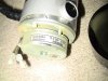
Most DC motors I've worked with have a red and black wire to indicate positive/negative, but with the wheelchair motor, it has 1 red/black thick wire, and then 2 small black wires, so 4 wires total.

After some reading around, people said that the 2 white wires, 2 black wires in my case, are used to stop the wheelchair from moving. But that's not my main issue.

My issue is, I'm trying to hook one motor up to a variable DC power supply (it supplies 15v max, with 2AMP) to just make sure the motor works before leaving this seller feedback and continuing on with my project. When I do hook the motor up to the power supply, the motor does not move at all, it just sounds like a short circuit is occurring, and I can see a little spark similar to when hooking car batteries up.

Now the motor is a 24VDC motor and supports up to 10A on a full load, so I'm wondering if I need to supply that much power to get the motor to move at all? In my experience, even if you don't supply the full 24VDC or whatever the motor is rated for, it will at least move, maybe at slower speeds, but it will move, but these two motors I cannot get to move at all, just sounds like the thing is braking or again a short circuit occurring...

So just looking for advice on what to do here?
 
The sparks make it sound like something inside of the motor is trying to run. Try giving it a good "push" while you have it powered up. If it still doesn't spin then you definitely have a problem with the motor, however if you can't even spin the motor by hand then your motor has seized up.
 
The sparks make it sound like something inside of the motor is trying to run. Try giving it a good "push" while you have it powered up. If it still doesn't spin then you definitely have a problem with the motor, however if you can't even spin the motor by hand then your motor has seized up.

I've got a pair of 24V wheelchair motors (only two wires though), and they can not be turned by hand. Pretty heavy duty gear head. Mine both worked well off 12V gel-cell battery, but way too much torque on start-up. I used aluminum angle stock, and bicycle chain, sprockets and wheels. They would flex the frame enough for the chain to jump the sprockets. Still sits in the corner of my shop, occasionally, I think about building a speed control, and microcontroller interface for it...
 
I've got a pair of 24V wheelchair motors (only two wires though), and they can not be turned by hand. Pretty heavy duty gear head. Mine both worked well off 12V gel-cell battery, but way too much torque on start-up. I used aluminum angle stock, and bicycle chain, sprockets and wheels. They would flex the frame enough for the chain to jump the sprockets. Still sits in the corner of my shop, occasionally, I think about building a speed control, and microcontroller interface for it...

Yeah see I have a 15V variable DC power supply, but that thing can only supply 2A, and my 24VDC motor says it supports 10A, so I'm wondering if I'm just not delivering enough power to this motor, and how many amps would I need to just get the thing to turn a little if any?

I can turn it once I put the wheel on it though by hand, but like Harvey said, I can't turn it without that wheel on it :)

I'm going to upload a picture here in a second as I want to make sure I'm hooking the right power supply wires to the right wires on the motor.
 
Okay, attached is an image of my female end of the motor connector piece.

Also, here is an image and details about this motor I purchased off eBay:

**broken link removed**
 

Attachments

  • IMG_0213.JPG
    IMG_0213.JPG
    531.6 KB · Views: 844
  • IMG_0214.JPG
    IMG_0214.JPG
    589.5 KB · Views: 1,054
It's quite possible the other two wires are a brake - I would expect the brakes to be normally on, and off when power is applied.

Try putting 12v or 24v on the other two wires.

I'd imagine you'll need more than 2A to start the motors, but I'm not sure.

A
 
It would probably be best if you could use something like a car battery to try to drive these motors. Then you know that you have the current that you need to drive the motor.
 
Okay, I got the 24VDC batteries (2x 12V) today, and got the same result. So as soon as I was about to give up, I turned the black little handle ontop of the gear box to the far right (you can see what I'm talking about here: **broken link removed**) which seems to lock the wheel, however, when I applied power to it this time, IT TURNED!

When you turn the black lever to the left, it allows me to turn the wheel with my hand, but if you turn it to the far right, it locks the wheel, so it would seem natural that you shouldn't have it turned to the right if the wheel appears to be locked, but that's not the case here...

So that was one nice discovery, however, there was 1 more to discover. Those 2 black connections in the middle are needed as well :) If no voltage is being supplied to those 2 middle connections, the motor will either not move, or move in a stepping slow motion. If you apply say 12V or higher, it's like it allows the motor to move freely like you would expect. So yeah, it seems those act as some type of relay or switch, but I also noticed as I turned the voltage down going to those two middle connections, it "slowed" down the motor, so I'm also wondering if they act as some type of speed control system...?

I still have a little more experiementing to do as it's been more of a trail and error to this point, but at least I know the motors do work.
I'm just a little concern that the far tip of the motor does get slightly warm when in use, but I'm guessing that's normal?
 
Last edited:
As I suggested earlier, it seems the middle two wires are a mechanical brake - that is how they can be used to slow the motor slightly.

The system uses a worm drive - a type of gear that cannot be backdriven. Thus, to roll the wheelchair along, you must disengage the gears. This is what the black handle is for - moving it to the left disengages the motors.

Obviously applying the brake makes it harder for the motor to turn, so it heats up. This is why the brake shouldn't be used to control the speed of the motor - only to stop the wheels moving by accident.

Andrew

Yeah the only thing I'm worrying about now is the amount of heat the motor is producing, as without a load it's still getting "almost" too hot to touch around the black pipe area. However, the wheel is still turning like normal, showing no signs of any issues, so do you know how warm wheelchair motors usually get?
 
I think I understand now why it's getting hot thanks to cowana and a little critical thinking.

Since there obviously is some type of braking mechanism built in, and the middle connections control that, in order for that brake to be fully lifted, it needs it seems 20-24VDC, otherwise, the brake will be either fully engaged or semi-engaged depending on how much voltage you are sending to those middle connections.

So this is what I did:

-I have a 12VDC Deep Cycle battery already, so I used that to control the motor (to get the wheel to turn)
-I purchased two small Lawn and Garden EverStart batteries today from Walmart, and I hooked those up in series to give me 24VDC

So I hooked the two Lawn and Garden batteries up to the middle connections to hopefully "fully" lift up the brake, and then hooked up the 12VDC to the motor and the wheel seem to rotate without any friction occurring from a brake or anything preventing it from moving.

This is still in a test phase since my motor is still hot from the first time I posted, so I need to wait until the motor fully cools down and give this another test to see how it does. But I think my theory is right, as when I unhooked the 12VDC battery from the motor, the wheel came down to a very smooth stop, instead of an immediate stop as if a brake was engaged.

I just wish more information out there was available so then I can know for sure how much power to send to those middle connections in order for the brake to be fully disengaged.
 
try having a look through the robot sites, battle robots use wheelchair motors and similar a lot.

Yeah I've been googling my little butt off for sure, and most people say that those connections are for a brake, but none of those sources mention how much voltage/current you need to supply to those middle connections in order to fully disengage the brake

As I'm sure I don't need all the AMPs my two EverStart batteries produce which is like 200+Amps hooked up in series, but I may need that 20-24v that they produced hooked up in series. I have a variable power supply too, and that only goes up to 15VDC and supplies only 2Amps max, and even that didn't fully disengage the brake, so I'm still sticking with my theory above your post and will retest it once the motor fully cools.
 
Last edited:
Okay, so after letting it cool down for about an hour (yeah it took that long lol), I put my theory to test and it works like a charm. However, I'm sure it doesn't require 2x 12VDC EverStart hooked up in series that are rated to have 200+Cranking Amps to disengage the lock as that would be nutts!

So I'm fairly sure it needs 22-24VDC, but not sure how many amps it (the brake mechanism) is pulling, so I guess that'll be my next test to see.
I did test to see if 1 12VDC EverStart would disengage the lock, but it did not, thus why I'm fairly sure it needs at least 22-24VDC to get the brake to fully disengage.
 
I would guess it would be the rated value of the motor - ie 24v.

Just had a brainwave: If the silver bands on the motors are the brush ports (and thus the back of the motor), I bet that the the black cap at the back of the motor is the braking system. Spinning the motor with the brake on makes this hot due to friction! A close up of this part of the motor and the silver band would help confirm this.

I am quite sure that the heat generated is due to friction, not motor overload. It can still damage the motor if too much is made - you don't want the brake melted on!

It might be possible to physically remove the brake somehow if you don't need it.

Just out of interst, when you apply 24V to the brake, can you hear a very quiet click? This could be the brake fully disengaging and hitting the rest-point-stop. If you can hear a click, see what the lowest voltage is that you can hear it on.

Hope I'm right!

Andrew

Yeah basically everything you've said here is what I've kinda sum'd up in the last 2 or 3 post lol. But yeah I can hear the click when applying the 24VDC and that let me know that the brake was fully disengaged. However, like I was saying earlier, if I don't apply enough voltage, it doesn't fully lift up the brake, thus causing friction, thus heating up the back of the motor that you was referring to.

I just need to figure out how many amps are required to lift the brake up fully, as I shouldn't need these two big batteries just to lift up the brake, but definitely need that 24VDC.

And about removing the brake, yeah that would be awesome if I knew what parts to disassemble to do that, but I don't want to mess up the motor trying to figure that out lol. I'll take some closer shots and upload them in a second here.
 
Okay attached are a close up of the cap off the tip of the motor which does appear to have a brake mechinsim under it. I tried hooking up the power to the brake connections, and I did see the silver part move a little, so I'm about 98% sure that piece is as cowana stated the brake part.

I'm now wondering if I just unhook the brown wires there will that disable the entire brake...on this motor... However, remember that in order for the brake to be "released", there has to be 24VDC going to it, so the only way to disable this entire motor from this motor, I "physically" need to take it out..

It also has a "oil" sticker on the front of it, but I'm not sure you can see that from the pictures I took.
 

Attachments

  • IMG_0216.JPG
    IMG_0216.JPG
    1.2 MB · Views: 3,421
  • IMG_0217.JPG
    IMG_0217.JPG
    686.8 KB · Views: 762
  • IMG_0218.JPG
    IMG_0218.JPG
    907.9 KB · Views: 830
Status
Not open for further replies.

Latest threads

New Articles From Microcontroller Tips

Back
Top