Hello again.
The 10K resistor worked a treat Mike.
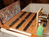
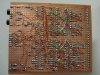
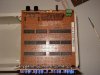
I have completed my circuit and have built it all on veroboard but now I have one problem which I completely overlooked before.
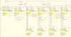
I have attached my diagram and the problem lies in the areas circled in red.
My problem is that I was going to use the terminal count output from U3 to trigger U4 which works but I didnt realise that pin 7 on U3 was going to be LOW for a minute wich is how long the number 9 on the previous IC is being held for. I was thinking of putting an inverter on Q3 of U3 to trigger the clock enable input from U4 on the negative edge but I dont think that will work because the inverter will only invert the logic state hence producing the same problem as before...am I rite? basicly I need to get an active low signal to trigger CE on U4 once only for a second and not be held for the entire minute The same need to be resolved for U5...can someone give me some hints on how to overcome this? By the way please ignore the switches on the diagram as I have connected them differently.
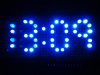
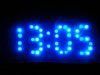
I will post pictures when this has been fixed...I made a custom 4 number 7segment display from 58 blue LED's and Im eager to see what you all think of it.
Thanks
The 10K resistor worked a treat Mike.
I have completed my circuit and have built it all on veroboard but now I have one problem which I completely overlooked before.
I have attached my diagram and the problem lies in the areas circled in red.
My problem is that I was going to use the terminal count output from U3 to trigger U4 which works but I didnt realise that pin 7 on U3 was going to be LOW for a minute wich is how long the number 9 on the previous IC is being held for. I was thinking of putting an inverter on Q3 of U3 to trigger the clock enable input from U4 on the negative edge but I dont think that will work because the inverter will only invert the logic state hence producing the same problem as before...am I rite? basicly I need to get an active low signal to trigger CE on U4 once only for a second and not be held for the entire minute The same need to be resolved for U5...can someone give me some hints on how to overcome this? By the way please ignore the switches on the diagram as I have connected them differently.
I will post pictures when this has been fixed...I made a custom 4 number 7segment display from 58 blue LED's and Im eager to see what you all think of it.
Thanks
Attachments
Last edited:


 .. sorry..lol) that changes the display brightness in different light conditions. It is two-state only (that is bright and dim) and includes a capacitor to avoid nasty display flickering when the light levels near the threshold.